This thread has been locked.

If you have a related question, please click the "Ask a related question" button in the top right corner. The newly created question will be automatically linked to this question.

LM5118: Is it possible to limit the input current for LM5118

Part Number: LM5118
Other Parts Discussed in Thread: TPS40210, LM5176, LM25118, LM317

Hi
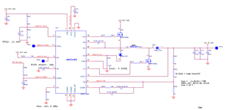
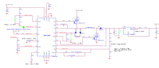
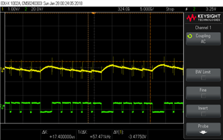
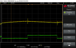
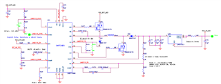
 I am planning this part LM5118 with input voltage 12V and 1A(max. input current) & Max. output voltage 25V with the current limit of 350mA. 

So I want to protect my input power supply by limiting the input current (or) output current by varying the output voltage similar to constant current control driving. 

Is it possible to implement these features?     Also one more point, In the datasheet One feature mentioned as Emulated Peak Current Mode Control

  • Hello Jaishankar,

    Thank you for using the E2E forum.
    Unfortunately, our engineers responsible for this part are currently out of office until the rest of the week.

    In the meantime, it would be helpful if you could send us more information on your planned circuit, like a schematic.
    You can also try out the design tools provided on the product page, including webench or the quickstart calculator, to compare your designs.

    The datasheet of the LM5118 lists a current limit feature, which means you should be able to implement your desired overcurrent protection.
    Emulated Peak Current Control mean an artificial current ramp is generated to reduce noise and improve stability of the system, even for very small duty cycles. A detailed explanation can be found on page 17 of the datasheet.

    If you only want to boost your input voltage from 12V to 25V, you do not even need the buck-boost function of the LM5118, and could use a boost topology instead to save the additional Mosfet and diode. An example for your requirements would be the TPS40210, which includes an overcurrent protection feature as well.

    Please let me know if you have additional question.

    Best regards,
    Niklas

  • Hi Niklas
        The input voltage will vary from 12-28V and the output voltage needed is 25V So I need only a buck-boost regulator.

    Method 1. In LM5118, Will this Emulated Peak Current control maximum input current or not? (As per the requirement mentioned above).

    Method 2. I thought of one more solution by adding one more external circuit using the INA301A1 part to achieve CC control. Please attached the Tina TI simulation file.

         Please suggest which Method (1 or 2) will give the expected result as mentioned above. 

    LM5118MH_cc control (1).TSC

  • Hi Jaishankar,

    the peak current control will measure the current through the inductor during the phase where the inductor delivers energy to the output.

    See 7.3.5 Current Limit in datasheet

    There are some reference designs which may give you some information as well which are close to your requirements:

    TI Reference Designs Library

    Checking your TINA file I am not sure if this would work - have you seen in the simulation the expected behavior ?

    In my opinion this will increase output voltage and therefore also the input current when the  INA detects an overcurrent.

    The LM5176 has an integrated control for average input or output current control.

    Best regards,

     Stefan

  • Hi Stefan,

        I have drafted the schematic which is attached below, Rsense(R218) resistor to Limit the current. So please check the shared your valuable feedback on the schematics.

      Additional Note: I have changed the LM5118 into the LM25118 part for cost optimization. So pls confirm this change won't create any issues.

  • Hi Jaishankar,

    i am not sure if this circuit will give you the expected behavior.

    Can you list your requirements in detail.

    What is the output current.

    How fast need the input current limit trigger to be.

    With the Rsense of 1.74Ohm the system would not work as the inductor peak current is always higher then 350mA

    Best regards,

     Stefan

  • Hi Stefan

    My requirement is to limit the input current below 1A(11,5V) & it should not cross the current limit because my supply can't handle it. 

  • Hi Jaishankar,

    let me have a closer look into this but I might need a 2-3 days.

    Best regards,

     Stefan

  • Hi Jaishankar,

    so to summarize
    Vin: 12 - 25V

    the max peak input voltage and max average input current is 1A.

    Output is:

    25V with ??? A  (max current at normal operation) - input current limited in case of failure to 350mA ?

    or 350mA with a max output voltage of 25V  ?

    Thanks,

     Stefan

  • Vin :11.5 - 28V

    Vout: 25V

    I need to only limited the input current within 1A limit. According to this input current limit, output current should be controlled (like a CV & CC control in the output)

  • Hi Jaishankar,

    in this case I recommend to use the LM5176 as this has already an average current limiting implemented.

    If you would like to stay with the LM518:

    As already mentioned above the approach you have made in TINA might also work but you need to feed in an increased voltage level when reaching the limit.

    Pulling FB low with trigger the controller to generate an even higher output voltage. Otherwise you can pull low the EN signal to shut down completely.

    Best regards,

     Stefan

  • Hello Jaishankar, 

    I have not seen an update on this thread for the last 7 days.

    If the issue is solved it would be great to press the is solved button.

    If there is still something open, just let me know with the new details.

    Best regards,

     Stefan

  • Hi

    sorry for the delayed reply.

    I plan LM5118(buck-boost) + LM317(as a current limiter) to get input current within the 1A limit. please check the below attached schematics share your feedback.

  • Hi Jaishankar,

    please limit the switching frequency to 350kHz (<400kHz) - this avoids some issues and make the design easier.

    -> R225 = 15.3k

    Some parameters should be adjusted - here the design calculator can help: LM5118 data sheet, product information and support | TI.com

    C_Ramp and R_Ramp needs also to be adjusted - see datasheet:

    C_Ramp: 10n

    R_Ramp 93k

    Some bulk output caps seems to be missing (e.g. 10uF - 20uF)

    Please also check your compensation - here again the design calculator can help.

    Beside that - I think this circuit will give you the required features.

    Best regards,

     Stefan

  • Hi Jaishankar,


    I have not seen an update on this thread for the last 24 days.
    So I assume the issue is solved.
    In this case it would be great to press the is solved button.

    If there is still something open, just let me know with the new details.

    Best regards,
     Stefan

  • While testing this actual circuit, I got the actual output voltage(25Volt) but I am hearing a noise from the inductor (in boost mode of operation).

    Please suggest a way to reduce the noise generated by Inductor.

    Thanks in Advance!!!!!!!!!!!!!!

  • Hi Jaishankar,

    can you please probe on the Switch nodes (both sides of the inductor). Can you see an oscillation here after the switching edge?

    In this case a snubber can help, see also additional info at the links below:

    Minimizing Ringing at the Switch Node of a Boost Converter:

    https://www.ti.com/lit/an/slva255/slva255.pdf?ts=1655709289212&ref_url=https%253A%252F%252Fwww.ti.com%252Fsitesearch%252Fen-us%252Fdocs%252Funiversalsearch.tsp%253FlangPref%253Den-US%2526searchTerm%253Dsnubber%2526nr%253D3296

    Calculate a Snubber:

    https://e2e.ti.com/blogs_/b/powerhouse/posts/calculate-an-r-c-snubber-in-seven-steps?keyMatch=SNUBBER

    Best regards,

     Stefan

  • Hi Stefan

      To reduce the noise from the inductor I tried to below items

        1. Increasing the Switching frequency (491kHz).

        2. Capacitance value increased of Ramp pin(0.1uF).

        3.  Increased the I sense resistance value to 150mE.

       By this, there is little reduction in noise from the inductor.

    Also, find the attached screenshot for both side inductors with respect to the output voltage.

    One side inductor Vs Output voltage(AC coupling).


    Another side inductor Vs Output voltage(AC coupling).

    Please advise further to resolve this issue........

  • Hi Jaishankar,

    can you please share your latest schematic - not sure if this is identical to the one show above

    Can you also please clarify with which component configuration the scope plots above have been made.

    Please confirm:

    - first plots are Channel1: output voltage / Channel 2: SW1

    - second plots are Channel1: output voltage / Channel 2: SW2

    What was the test condition there: input voltage  and load?

    Is channel 2 AC coupled or DC coupled?


    Best regards,

     Stefan

  • Latest schematics

    Pls find the inline responses......

    - first plots are Channel1: output voltage / Channel 2: SW1       >> Yes

    - second plots are Channel1: output voltage / Channel 2: SW2    >> Yes

    What was the test condition there: input voltage and load?       >> 12V input & max load current controlled by LM317

    Is channel 2 AC coupled or DC coupled?      >> Channel 2 is DC coupled Only channel 1 is AC coupled.

  • Hi Jaishankar,

    i put your design into the quick start calculator tool (can be found on the product page) and got very different values for the RAMP configuration:

    Cramp = 500pF    Rramp = 93k

    Can you please check with that values again. The voltage ripple on the Vout is much to high.

    Please also keep the switching frequency below 350kHz - this can avoid issues as already mention above.

    Rt = 15.27k

    Best regards,

     Stefan

  • Thanks you so much.....

    With this two changes noise is now inductor noise is removed completely. Maximum output ripple voltage is 300mV.

    But still there is one issue I am facing was during Under Voltage condition. Input for this IC is coming for 6meter long cable which can handle upto 1A.

    When under voltage reached(10.45V) LM5118 is disable & input current become zero. With this current again input voltage rise(due to long cable) LM5118 enable again. This is creating an continuous oscillation in Enabling the IC.

    Please suggest a way to correct way to implement undervoltage protection.

  • Hi Jaishankar,

    so you would need to increase the hysteresis of the UVLO detection.

    Maybe this report gives some ideas on how to solve this:

    Adding Hysteresis to Supply Voltage Supervisor (ti.com)

    Best regards,

     Stefan

  • Hi Jaishankar,


    I have not seen an update on this thread for the last 13 days.
    So I assume the issue is solved.
    In this case it would be great to press the is solved button.

    If there is still something open, just let me know with the new details.

    Best regards,
     Stefan

  • Thanks for your support. Now everything working fine ThumbsupThumbsupThumbsup

    Now I am doing thermal testing for the complete circuit