- Ask a related questionWhat is a related question?A related question is a question created from another question. When the related question is created, it will be automatically linked to the original question.
This thread has been locked.
If you have a related question, please click the "Ask a related question" button in the top right corner. The newly created question will be automatically linked to this question.
With a single cell configuration, I am using a 5V/3A adaptor on VAC1 input but cannot get the BQ to charge the cell even though it reports it is charging (STAT LED on and ADC control reg 0x2E bit 7 set to 1). IBAT current remains reported as 0mA, yet an inline amp meter (with the battery), shows a constant _drain_ of about 160mA.
I did not hot-swap the battery nor inadvertently reversed the leads to it. Just started working with this chip a few days ago - seems overly complicated or I am making some dumb mistakes here. Help appreciated.
BQ25792 dump
Register Hex Binary
REG 00 : 0x0C 00001100b
REG 01 : 0x01A4 0000000110100100b
REG 03 : 0x00C8 0000000011001000b
REG 05 : 0x2D 00101101b
REG 06 : 0x008F 0000000010001111b
REG 07 : 0x8F 10001111b
REG 09 : 0x05 00000101b
REG 0A : 0x23 00100011b
REG 0B : 0x00DC 0000000011011100b
REG 0D : 0x4B3D 0100101100111101b
REG 0E : 0x3D 00111101b
REG 0F : 0xA2 10100010b
REG 10 : 0x80 10000000b
REG 11 : 0x40 01000000b
REG 12 : 0x00 00000000b
REG 13 : 0x41 01000001b
REG 14 : 0x96 10010110b
REG 16 : 0xC0 11000000b
REG 17 : 0x7A 01111010b
REG 18 : 0x54 01010100b
REG 19 : 0x008F 0000000010001111b
REG 1B : 0x0B 00001011b
REG 1C : 0x6A 01101010b
REG 1D : 0x01 00000001b
REG 1E : 0x50 01010000b
REG 1F : 0x00 00000000b
REG 20 : 0x00 00000000b
REG 21 : 0x00 00000000b
REG 22 : 0x00 00000000b
REG 23 : 0x00 00000000b
REG 24 : 0x00 00000000b
REG 25 : 0x00 00000000b
REG 26 : 0x00 00000000b
REG 27 : 0x00 00000000b
REG 28 : 0x00 00000000b
REG 29 : 0x00 00000000b
REG 2A : 0x00 00000000b
REG 2B : 0x00 00000000b
REG 2C : 0x00 00000000b
REG 2D : 0x00 00000000b
REG 2E : 0x80 10000000b
REG 2F : 0x00 00000000b
REG 30 : 0x00 00000000b
REG 31 : 0x0000 0000000000000000b
REG 33 : 0x0000 0000000000000000b
REG 35 : 0x1508 0001010100001000b
REG 37 : 0x1502 0001010100000010b
REG 39 : 0x0000 0000000000000000b
REG 3B : 0x0FD2 0000111111010010b
REG 3D : 0x0F96 0000111110010110b
REG 3F : 0x0253 0000001001010011b
REG 41 : 0x003C 0000000000111100b
REG 43 : 0x0000 0000000000000000b
REG 45 : 0x0000 0000000000000000b
REG 47 : 0x00 00000000b
REG 48 : 0x08 00001000bvbat 0x0FC0 :4032 mV
ibat 0x0000 :0 mA
vbus 0x1511 :5393 mV
ibus 0x0000 :0 mA
vsys 0x0F8E :3982 mV
vac1 0x150E :5390 mV
vac2 0x0000 :0 mV
I tested your register file into a BQ25792 EVM and it works fine. The inline amp meter might be causing issues with it's series resistance. Have you tried removing the current meter?
By the way, I would advise against setting VSYSMIN higher than the charging voltage. Once the voltage input is disconnected, the battery charger will not be able to sustain VSYSMIN and the voltage will fall to the battery voltage.
I did remove the amp meter and the results are the same. Once I remove VAC, I can no longer communicate with the device, so this means i2c is not functioning when on batt power? All in all this looks very fishy, smells like a busted chip to me!
I see. I don't think the chip is busted yet. It maybe the input mosfets. Can you short jumper JP3? This will connect VAC1 directly to VBUS and bypass the input mosfets.
I've spent another day poking at this thing, VAC bridged or not, using input 1 vs 2, nothing makes sense of the data I am seeing. As a matter of fact the chip now reads voltages that are below 2.5Volt (Vsys, VBatt) even though it is powered by a nice steady 5.2V/3A on VAC input and a 3.8V 18650 in place. Seems this chip is toast indeed. Nice! What a waste.
There's a few more tests that need to be run before that.
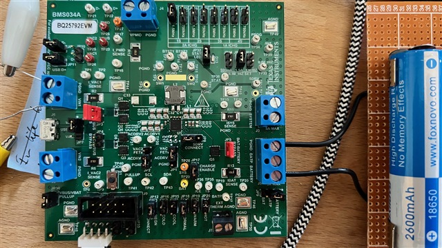
Can you send a picture of the board so I can check to make sure the jumpers are in the right place?
With battery only attached, does BAT TP measure the correct battery voltage? If so, does SYS = BAT? If that is true, can you communicate via I2C?
If you can communicate via I2C, don't change an registers and attach VBUS. Can you measure switching at SW1 or SW2?
Without Vac connected, according to the BQ25792, Vbat is sitting at 3.79 volt and Vsys at 3.76. A DVM shows 3.81 measured at the battery. Without Vac input I2C is functional. I am not getting the chip to charge the battery (even though the LED is on), in fact the battery is slowly discharging through the EVM. Picture of EVM is attached.

Your jumpers are in the right position. When you attach VBUS, can you measure switching at SW1?
With no power applied, can you also measure the resistance between VBUS to GND, REGN to GND, PMID to GND, VBAT to GND, and SYS to GND?
With VBUS connected and a mostly charged batt installed, SW1 is at a constant 2VDC. Without a battery or a mostly discharged battery, SW1 switches between 0 and 2VDC in somewhat irregular intervals of 600ms - what is this signal supposed to look like?
Without VBUS nor battery installed, R values are:
VBUS - GND: not getting a solid R reading. Something is charging/discharging, R reading between 500k and several meg
REGN - GND: 4k7
VBAT - GND: 31E
SYS - GND: infinity / very high.
The chips is definitely dead then. VBAT to GND should measure about 1 Megaohm. I'll take care of the replacement.