This thread has been locked.

If you have a related question, please click the "Ask a related question" button in the top right corner. The newly created question will be automatically linked to this question.

LM5009: LM5009 rebootstrap issue

Part Number: LM5009
Other Parts Discussed in Thread: LM5019, LM5164, LM5163

Dear TI expert,

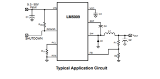
Application Description

1) 75VDC Vin  --> LM5009 buck (output 14V) --> LDO TPS70933 (output 3.3V)

2) LM5009's load are feedback resistor (47K+10K)  and LDO (3~4mA). 

Issue Description

Step 1: When 75VDC Vin switches off, LM5009's output 14VDC signal  s dropping slowly due to the load is light.

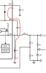
Step 2: When LM5009's output 14VDC signal  is dropping at 2.5VDC, 75VDC Vin  switches on again, LM5009 can't rebootstrap  due to LM5009's output 14VDC signal  is not zero.

Finally, LM5009's bootstrap pin keeps as 6.5VDC and LM5009's output 14VDC signal keeps as 2.5VDC steadily.

My question:

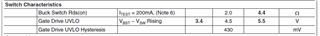
1) Even if LM5009 is at the Gate drive UVLO status, there is still a small current goes to load ? If yes, how much of this leakage current or discharge current ?

  • HI 

    we don't have the leakage current value of LM5009,  boot capacitor can't been charged due to diode not fully conductor. you may need adding some dummy load or increase the load current so that the diode can conductor so that the boot can been charged.

    one alternative solution is using LM5019, cause it is synchronous converter , it won' t have this issue. 

    Thanks

  • Hi Daniel,

    Which diode ?

    Thanks.

    BRs

    Xiangdong

  • HI

    D1, freewheel diode

  • Sorry, I don't catch your point.

    The current direction of load is from Vout to GND. How to achieve the conducted D1 ?

    My understand is that  if Vout is 2.5V which will cause gate drive is about 4V which is less gate drive UVLO requirement, as shown below.

    gate drive  4V = LM5009 VCC 7V - Vout 2.5V - forward voltage of internal diode 0.5V

    Can you help me to check or clarify it in detail and ASAP ? 

    Thanks in advance.

  • HI 

    when high side is on , SW=VIn, the boot voltage is Vin+Vboot which will higher than VCC which block the inner diode to charge the boot.

    when high side off, diode will conduct if load current is enough, so SW=-0.6, Vcc higher than Vboot, it allow charge current.

    but if D1 does not conduct which cause  SW+boot UVLO voltage higher than VCC, it will block the boot capacitor be charged.

    1-D time of light mode, SW will be equal to Vo , so when Vo higher than 2.5V , boot votlage will be lower than 4.5V which is its UVLO threshold.

    pls add some dummy load to increase the load current so that D1 can conduct at 1-D time in light load condition so that boot can be charged.

    thanks

  • Hi,

    Thanks for your comments.  Of course, if LDO TPS70933 is working, the min. load can be guaranteed and LM5009 can works as your description.

    But there is a low power consumption requirement in our application, that's why we don't want to add a big dummy current at feedback circuit.

    What is the conducting time requirement of D1 at 1-D time or min. load current for the Vout is rising or dropping at 2.5V before LDO TPS70933 works ?

    Thanks in advance.

  • Hi 

    I think for low Iq application, LM5163 or LM5164 is fitting and both don't have boot issue. This issue is always happen in asynchronous and high voltage output condition.

    you can try to reduce the inductor value let the peak current high to see whether it can force diode conduct. 

    Thanks

  • Thank you for your support. 

  • HI

    I will close this question, if you have further question, you can reopen it again