This thread has been locked.
If you have a related question, please click the "Ask a related question" button in the top right corner. The newly created question will be automatically linked to this question.
Hi Team,
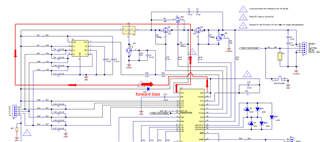
I checked the bq40z50 spec to see the suggestion for BAT pin as the following.
"Replace D1 and R13 with a 10 ohm res istor for single cell applications"
But I found the other E2E thread(see Here-BQ40Z50: bq40z50 1s) which seems to conflict with spec. May I know if user can use one resistor (10 ohm) only for 1S application?
Hello Cheer,
I think both are valid, if the customer would like use 1S configuration, they may need to remove the diode to operate at a lower voltage. This does take away the protection that Swami mentioned where it prevents accidental charging of the batteries.
There are other gauges that are better designed for 1S, like the newer BQ27Z746.
Sincerely,
Wyatt Keller
Hi Wyatt,
Could you elaborate on "prevents accidental charging of the batteries" & "The main purpose of the D1 diode is to prevent accidental charging through the path from Vcc to BAT"? I really don't know why the Diode can prevent the charging. As I know, it should be "forward bias" from Vcc to BAT always, like the following
How can it be protected? I'm not sure if the diode might be protected for a short event, such as BAT will be pulled to the ground when Pack+/- being short.
Thanks for your suggestion on bq27Z746 but end customer would llike to use SMBus.
Hello Cheer,
There may be a small current path through VCC even if the FETs are off, I believe that is the intended use of the diode is to prevent the small current flow through VCC to BAT. If there is only a resistor it would not prevent this.
Sincerely,
Wyatt Keller
Hi Wyatt,
A). May if know how many current will through VCC to BAT if the customer only use a resistor(10 Ohm) for BAT (same as SPEC's method)? Or how to claculate this current?
B). If BAT only use a resistor(10 Ohm) and then the charger attached always, It seems to have this current flow always even the gauge enters any protection to turn off CFET(such as OVP, OCCP, OTC), right?
Hello Cheer,
I am checking with the design, I'll let you know the feedback.
That would be the suspected issue, is even though CFET and DFET are open there could be some current flow. I have not personally tested this and I have asked design.
Sincerely,
Wyatt Keller
Hello Cheer,
This was the feedback from the design team:
There is no path for current to flow between VCC to BAT, but if there was a fault in the IC between VCC/PACK and BAT, the reverse current path would be blocked with an external redundant component (the diode). That’s the purpose of the diode, it’s for safety to avoid a sneak charge path. It just isn’t practical to add in a single cell application.
Sincerely,
Wyatt Keller
Hi Wyatt,
Got it, thank you very much. So, bq40z50 can only use one resistor(10 ohm) on BAT instead of the diode in single cell appplicatoin.
Hello Cheer,
Correct, you can use 10ohm resistor instead of diode.
Sincerely,
Wyatt Keller