This thread has been locked.

If you have a related question, please click the "Ask a related question" button in the top right corner. The newly created question will be automatically linked to this question.

LM76003: Current limiting and SW Frequency Fail

Part Number: LM76003
Other Parts Discussed in Thread: TAS2552, , LM76002, , LM76005-Q1, LM76005

A small run (600) PCBA's with LM76003 as 3V3 rail from a 30..42 volt battery supply with a TAS2552 audio chip included. On quite a few (say 4%) of the boards, audio failed to start and failed MTE. Turns out the audio chip was just  resetting due to a brown out of the 3V3. The audio chip would draw around 2.5 Amps normally.

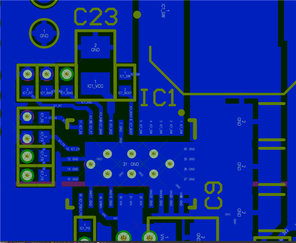
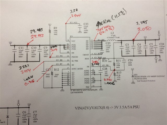
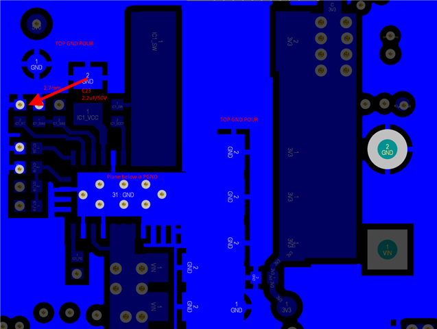
  • Schematic and SW/Freq pics included
  • Static 2.5A load test results in rail being pulled down to 1.63V and staying there.
  • RT resistor is normally unpopulated
  • Bad board Fsw is ~750KHz
  • Good board Fsw is ~500kHz
  • All passives were removed and checked (except 4u7 inductor). No improvement.
  • RT resistor changed from DNP to 82kohm and Fsw was now ~530kHz and SW waveform looked normal but CL issues persisted.

We have not reworked the LM73006 on the PCBA's (mainly because you can't lay your hands on TI parts these days) but visually and via xray, they look OK.

Any thoughts appreciated, I am thinking "IC start-up" since we have anecdotal evidence of the Audio starting correctly occasionally on some of the boards. But I have not seen this myself.LM76003_CL_Issue.zip

  • hi, 

    I have checked the SCH is good.

    The yellow line in PNG BrownOut_AudioEnable in designed output of LM76003? it looks like device is power down then restart again, do you consider it as thermal issue.

    And dose it mean LM76003 could not handle 2.5A load  ?

    Do you have a EVM at hand or other PCB ,could you move issue parts on EVM to check. 

    Elena

  • Elena thanks for responding.

    Yellow line on BrownOut_AudioEnable.png is the 3V3 rail when audio chip attempts to generate audio (draw 2.5A) You see the 3V3 rail droops and it goes below the TAS2552 reset level of 2.45V - so Audio chip resets and no longer draws 2.5Amps and the rail returns to normal level. 250us is too quick for any thermal concerns. To prove it was  current limit issue I attached a resistive load of 1.3ohms with a pb switch. When you close the switch the rails falls to 1.63V  and remains there until switch is opened (static load test mention previously). So yes, the LM6003 cannot provide 2.5Amps on PCBA's that exhibit the problem. On good PCBA's the rail remains at 3.3volts of course.

    I do not have a an EVM on hand, but we have built 600 PCBA's with this design and only about 4% show this problem. I have checked the passive components (except the inductor) by moving to other working boards -> OK.

    I will check the inductor tomorrow as this may affect valley CL, to confirm that part is not causing the problem.

    Can you explain why, when RT pin is left floating, the failed PCBA's run at 750kHz and the good PCBA's run at 500kHz as expected?

    Mark

  • hi, Mark,

    The switch frequency is controlled by RT and sync, Under you application RT is floating, so is there some signal near sync pin may have impact the sync?

    another idea is ,we have a LM76003and LM76002, 2.5A is just LM76002 current limit .have you try a good unit on bad PCB ,but it looks like you can't do solder work on it .

    Elena

  • Here's the layout - next layer down is GND plane SS and RT components are DNP, no signals near by - also, all good boards are @ 500kHz and they have same layout/signals around them.

    Definitely "LM76003R" on the IC. If I had new LM76003 parts I would have reworked, I will try rework with recovered parts. Let you know.

    Thanks

    Mark

  • SYNC pin is grounded - see SHC

  • OK, let see if new chip could help.

    Have you try to submit a FA from TI.com, could you share which customer your are support or what filed used. I leave my add here in case something you do not want to public. elena-gao@ti.com

    Elena

  • I am reluctant to replace the chip because that is ambiguous and replacing with a working chip tells me nothing - I am trying to learn from the faulty board.

    I swapped out the inductor - no change (so that is all external parts verified)

    Last question and then you can close this topic.

    Note the pic above, "working" PCB [black], failed PCB[red], both boards function correctly except all the values I can measure (including current limit) are lower on the failed PCB.

    In particular can you find out under what circumstances the LDO would put 2.9V (under a 1Amp load, so in PWM mode) when the datasheet states it should be nominally 3.29V?

    I suspect this low VCC causes lower on chip reference and so lower output voltage and lower current limit. The clue is in the FB divider, the board puts out stable 3.05 volts at ~1Amp here and the FB pin is stable at 0.930V

    Why would this be so based on what you know of the IC's design?

  • looks like VCC=2.9 is out of vcc L_limit, but Ven =1.2V is only reason lead to Vcc goes lower. 

    Elena

  • Apparently not the "only" reason since EN is connected to VIN - Do you have anyone who knows this chip you can contact?

  • hi, 

    I will loop my team member to see if they have some ideas. please wait.

    Elena

  • Hi Mark,

    The 3.3Vout and Fsw=500KHz, the suggested Cout is 150uF after derating, now the Cout cap voltage rating is 6.3V, effective capacitance maybe drop to 60%.

    On the PCB layout, how is VCC cap C23 grounded? VCC cap should be grounded to PGND with shortest routing. can you show more big layout area?

    B R

    Andy

  • Andy,

    I added a couple of more 47uF/6V3 caps on top of the existing output is still 3.05V from 10mA out to around 1.5A load. VFB remains at ~930mV over that load range. If I change FB resistor to 39k from 43.2k VFB REMAINS at ~930mV but VOUT is now 3.39V.

    What cause LDO VCC and VFB to be out of spec?

    Datasheet does not mention closest route to PGND for VCC cap but PGND is the entire plane below and the route is ~2.7mm from the VCC cap to two vias to PGND, so should not be an issue.

    Also I disconnected BIAS input from VOUT and connected it to PGND - no change.

  • Hi Mark,

    Pls check it with your vendor if these chips were supplied by TI certified distribution channel.

    B R

    Andy

  • PCBA's were assembled in China, the CM sourced the parts - I will make enquiries, thanks. Any ideas if certified stock exists anywhere - at least enough to rework the failed boards (20-30)?

    Thanks for your help on this - I will infer from this discussion the parts we have are potentially "seconds"/rejects

  • Hi Mark,

    Pls check if there is stock in DigiKey or Mouser? or contact distributor Arrow

    B R

    Andy

  • No stock with realistic or trustworthy prices, can I use the LM76003-Q1 part as a direct replacement?

    Thanks Elena and Andy for your help on this, you can go ahead and close this question out.

  • LM76003-Q1 can be direct replacement, and you even can try it with LM76005 or LM76005-Q1.

    I will close this thread.

    B R
    Andy