This thread has been locked.

If you have a related question, please click the "Ask a related question" button in the top right corner. The newly created question will be automatically linked to this question.

TPS61099: Low output capacitance

Part Number: TPS61099

Dear all,

We have a design with TPS610995 and the LOAD powered from this dc/dc regulator needs that its power supply voltage changes from 0 to 2.1 V in less than 1 ms. As the dc/dc has a softstart and the LOAD needs 100 uF input capacitor, we are not able to meet this requirement. We took some measures and rise time was around 3.3 ms.

So, is it possible to deactivate softstart or have a version of this dc/dc without softstart?

We have reviewed the TPS610995 datasheet and we could see that the output capacitor must be between 10 uF and 100 uF. However, in the Capacitor selection we found the following sentence: " The TPS61099x is optimized to work with the inductor from 1 μH to 2.2 μH, so the minimal output capacitor value is 20 μF (nominal value). Increasing the output capacitor makes the output ripple smaller in PWM mode." 

Assuming we cannot deactivate the softstart, we reduced the output capacitor to reduce the rise time. Now we have a 2.2 uH coil and approximatelly 10.6 uF output capacitor formed by several capacitors. The output voltage is 3.6 V and the maximum peak output current will be 800 mA. Input voltage can vary between 3.6 V and 2 V. The load can work from 2.1 V to 4.2 V.

So, which problems could we have with this configuration (output capacitance of 10.6 uF)? Do you recommend to increase a little more the output capacitor up to 20uF?

Best regards,

  • Hi Mayte,

    TPS61099 switch peak current limit minimum spec is 0.8A.

    Please note that for a boost converter, the switch peak current normally represents the maximum input current level. This device cannot output 800mA load current in boost mode.

    From your description that Vin varies between 2V and 3.6V and output voltage varies from 2.1V to 4.2V, I suggest use select a buck-boost converter.

  • Hi Zack,

    Sorry I meant output current 0.5 A.

    Regarding voltages, this design was done for an old version of the load that only accepted voltages between 3.3 and 4.2 V with a typical voltage of 3.6 V. The input voltage can be from 3.6 to 2.1, but we are currently using batteries with voltage range between 3.2 V and 2 V. We already have the design and we did not want to perform any changes right now.

    My question was more related to the output capacitor, so, with 0.5 A output current, a minimum of 2.3 V input voltage and 3.6 V output voltage, is it ok to use only 10 uF if we are using a L=2.2 uH? Or we should use 20 uF?

  • Hi Mayte,

    Thank you for clarifying your applications.

    You mentioned the output capacitor 10uF is formed by several capacitors. For this device output capacitor selection, the concern is with a not high enough output capacitance, the loop stability issue may happen. 

    If you don't care about the output voltage AC ripple and still want to use 10uF cap, you can try below load transient test to verify the loop phase margin is high enough.

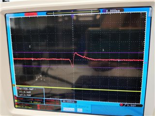
    Set the VIn at minimum 2.3V, run the load transient test: 0A <-> 0.5A, probe Vout AC waveform. If the Vout doesn't have any oscillation, it means the phase margin is higher than 45 degrees.

  • Many thanks for your answer.

    I already tested what you are suggesting and the output waveform is the one in the picture below,  does this mean that the phase margin is LOWER than 45 degrees?

    On the other hand, I finally decided to add 2 additional 4.7 uF  capacitors in parallel at the output so the output capacitance is more in line with your recommendations.

  • Hi Mayte,

    Yes, I would recommend you add two more 4.7uF ceramic capacitor to avoid loop instability problem. 

    Let us know if you have any further questions.