This thread has been locked.

If you have a related question, please click the "Ask a related question" button in the top right corner. The newly created question will be automatically linked to this question.

BQ27520-G4: BQ27520

Part Number: BQ27520-G4
Other Parts Discussed in Thread: BQSTUDIO, BQ27520EVM, , GPCCHEM, BQ40Z50
Hi Team,
Here we are using the TI device BQ27520EVM & a TI software Battery Management Studio (bqStudio) in the EVM Setup.
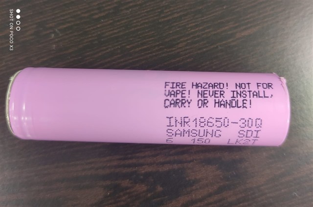
1.We are using Samsung INR18650-30Q button cap battery instead of a battery pack and don't have an NTC inbuilt. In our device We are planning to add NTC on our battery compartment.  With the help of a mechanical switch, it is able to detect battery removal, but Our concern is where to connect this Battery removal switch? please advise.
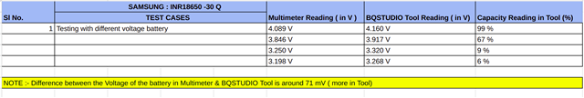
2.When a low capacity Battery is charged to 80%, and removes the charger first and then battery and reinserts the same battery again into the device. then the capacity reading shown is entirely different, for eg : instead of 80%, it shows 50%. 
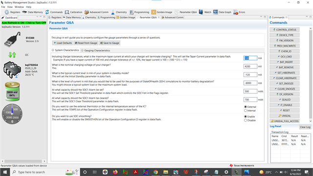
FIg1 : Capacity = 84% while charging.
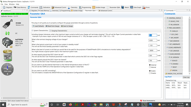
FIg2 : Charger Removed and battery Re-inserted, capacity = 46%
Device configurations
Please go through the below Configurations we have done and assist us if anything is wrong.
1. Gauge characteristics and system characteristics as follows.
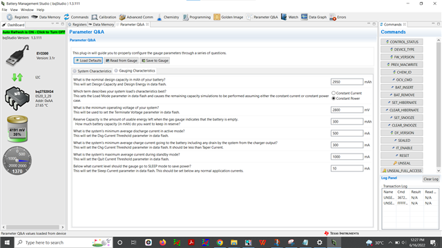
                               FIg3 : Gauge characteristics
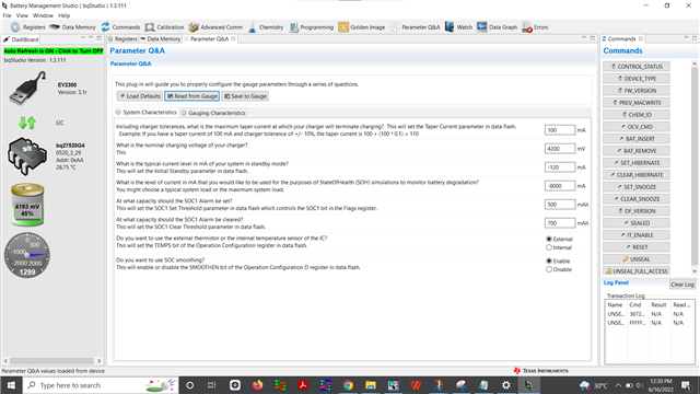
                         FIg4 : System characteristics
2. Selected the cell chemistry as per the battery datasheet.
                                          Fig 5 : Cell chemistry
3. in the Data memory (design capacity ,taper current and taper voltage)as given below.
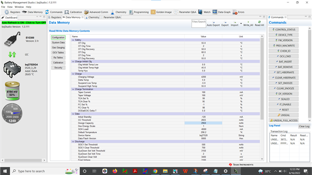
           Fig 6 : Data memory
BQ27520-G4 -------- Fuel Gauge IC
----------------------------------------------------------------------------------------------------------------------------------------

BQSTUDIO (Battery Management Studio) --------- Software Tool Used
BQ27520EVM -------------- Evaluation Module Used

EVK Setup includes :-
-----------------------------------------------------------------------------------------------------------------------------------------
1. BQ27520EVM ( Evaluation Module )
2. EV2300 (USB TO I2C interface connector)
3. I2C cable , USB Type-C cable
4. Battery
5. Load
6. Charger

TI devices used :-
-------------------------------------------------------------------------------------------------------------------------------------------
1. BQ27520EVM
2. EV2300
Issues:-
-------------------------------------------------------------------------------------------------------------------------------------------

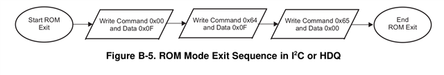
1. Followed the bqstudio flow chart but not worked.

• How to configure Parameters Q & A ( System characteristics & Guage Characteristics values )
• Since EVM comes precaliberated , we do not want to cliberate the gauge right. But if we are using our own board how to caliberate?
• If the cell chemistry Description is different, whether there is any issue? (Our's is Lithium Ion Rechargable Battery)
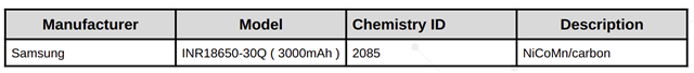
Manufacture :- Samsung ; Model :- INRI8650-30Q (3000mAh) ;
Chemistry ID :- 2085 ; Description :- NiCoMn/carbon
• What do you mean by discharge at C/5 ?
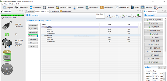
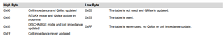
• UPDATE_STATUS data flash register is not showing the value as 2
• How to write Ra Table, Qmax, Cycle Count & Update Status to gauge ?

  • Hello Jerin,

    Are you using the BIE function of the gauge for battery insertion detection? The functionality is explained in the TRM: 5.3.3 Battery Presence Detection Using the BI/TOUT Pin

    The parameters in the Q&A section is based on the cell you are using and your other system specifications like the charger you have, we cannot assist with these settings as it is system dependent.

    You should use the calibration tab in BQStudio for calibration of custom board. You can also average a sample size and use this in your golden image for production level programming.

    I'm not sure I understand, if you have the exact cell as what is in the chemistry ID database, you can use that cell. If it's not in the database you should use the GPCCHEM tool to find the best match.

    C rates are commonly used in battery terminology, please check here for more info: https://batteryuniversity.com/article/bu-402-what-is-c-rate

    You should not write to any of the registers you mentioned, the gauge updates these automatically. You need to run a learning cycle before any gauging parameters are correct (like RemCap FCC, SOC, etc)

    Sincerely,

    Wyatt Keller

  • Hi Wyatt,

    We are using BIE function of the gauge for battery insertion detection.Steps we followed is as below

    1.UNSEAL full access command,IT_ENABLE command and RESET 

    2.Programmed  the chemistry ID by selecting the corresponding battery from the chemistry database(Samsung INR18650-30Q)

    3.Set the Various Configuration Parameters in Data Memory. Below are the Configurations.

    • Design Capacity - 3000 mAh
    • Charging Voltage - 4275 mV
    • Taper Current - 250 mA
    • Taper Voltage - 350 mV
    • Discharge Current Threshold - 60 mA
    • Charge Current Threshold - 75 mA
    • Quit Current - 40 mA
    • Terminate Voltage - 2800 mV
    • Qmax Cell 0 - 3000 mAh
    • Qmax Cell 1 - 3000 mAh
    4.Discharged at C/5
    5.Relaxed for 5hrs
    6.Charged at c/2
    7.Relaxed for 2hrs
    8.Discharged at c/5
    9.Relaxed for 5hrs
    we tried 3 learning cycles.But still update status is showing as 0x00.Do we need to check any other configurations?
  • Hello Jerin,

    Can you share the BQStudio logs of your learning cycles along with the .gg from before and after?

    Also your procedure seems like there may be some steps out of order, if you seal the gauge, then unseal in order to change the IT_ENABLE, after the RESET it will seal the gauge again and you cannot update any flash.

    Sincerely,

    Wyatt Keller

  • fuelgauge.log

    Hereby attaching the log file.

  • Hello Jerin,

    It looks like you are discharging with a constant resistance load instead of a constant current load. The gauge will not update resistance if the current is outside the range of C/5 to C/10 in learning.

    This gauge has a cell detection feature that needs to be set properly to complete a QMax update. By default it’s on but will interfere with QMax updates. Set OpConfig[IDSELEN] to 0 or run cycles until Flags[WAIT_ID] is 0 (this is 1 all the time in the log file so the gauge still hasn’t figured out what cell was inserted).

    Sincerely,

    Wyatt Keller

  • Hi Wyatt,

    We have successfully got the UPDATE_STATUS from 0 to 2. And we extracted the golden image.We created golden image twice (5 minutes after first golden image creation ). And now the md5sum of both the .df.fs file is different. Could you please explain the reason ?

    Hereby attaching the .df.fs file

    1157.Golden_image.zip

    0520_3_29-bq27520G4.df.fs_1 -------> First created golden image (.df.fs)

    0520_3_29-bq27520G4.df.fs_2 -------->Secondly created golden image (.df.fs)

  • Hello Jerin,

    I'm glad to hear you got the learning completed.

    There are multiple reasons that the flash streams are not the same, any small change in the dataflash and they will not be an exact match. If anything in the 4.5 Data Flash Summary is modified it will change the DF.FS, we also have internal variables the gauge uses and those can be modified as well by the gauge between the two exports.

    Sincerely,
    Wyatt Keller 

  • Hi Wyatt,

    We got the update status 0 updated to value 2.

    Please check this screenshot : 

    Now we are continuing this cycle for updating update status 1 to learn.
    I need your confirmation on below questions: 
    1. I am attaching a golden image for your reference, Can you please give your confirmation that everything is updated correctly or not?
    2. We are still not sure why It took around 6 complete cycles to update the status. That is why we need your help to check the golden image thoroughly.
    Hereby attaching the golden image.
    Thank you.  
  • Hi Wyatt,

    We have one more doubt regarding the update status. 

    The update status in the OCV Tables ( OCVa0 Table & OCVa1 Table )  are not updating. Could you please explain the reason ?

    Hereby attaching the screenshot. Please check this :-

    Sincerely,

    Jerin Jose

  • Hello Jerin,

    I will not be able to determine the cause only from the golden image, if the Ra table and Qmax are changed from the default and the update status is good then it has done it correctly. The reasons for the failures is most likely related to the feedback I mentioned after reviewing the logs.

    As long as the update status in the State class updated the learning is good.

    Sincerely,

    Wyatt Keller

  • Hi Wyatt,

    We have a doubt regarding Flashing the generated Golden image. While executing the generated golden image flash stream file from the NXP some of the register read-write is not happening . In the Data Block, Read and Compare command C is not reading the correct value. ( eg. C:166600 instead of reading 66 it is reading as 29 ).  Can you please provide the reason for this issue ?

    Sincerely,

    Jerin Jose

  • Hello Jerin,

    There is not enough information for us to determine the reason for the issue, some of the common issues during flash stream programming are:

    Not enough time between commands (increase the X: terms to 5-10ms).

    There are power fluctuations causing bad flash write.

    Issue with the driver code to program the flash stream. If you use BQStudio and it works then this may be the case.

    Sincerely,

    Wyatt Keller 

  • Hi Wyatt,

    We got stuck in ROM mode after trying to program with flash stream.  ie device is giving acknowledgement from the address  0x0b,not 0x55.Even BQSTUDIO is tool is not able to detect fuel gauge.We tried to exit form rom mode using the following i2c commands

    i2cset -y 0x0b 0x00 0x0f

    i2cset -y 0x0b 0x64 0x000f w

    sleep 4

    After that the device was giving acknowledgement from  0x55, but when we restart the gauge the address was back to 0x0b.That means device is again moves to rom mode.

    Can you please provide the steps to exit from rom mode  ?

  • Hello Jerin,

    The device should not boot up in ROM mode unless there is an issue with the firmware upload. I would try re-uploading the firmware using the TI toolchain and then testing if it goes to ROM mode on wakeup.

    Sincerely,

    Wyatt Keller

  • Hi Wyatt,

    The issue was resolved. Now the device is showing acknowledgement from the address 0x55.

    We connected the setup to the BQStudio tool and we used the .SREC file to re-program the device. It seemed to work, after which we clicked the "execute firmware" button in BQ studio. Is there any problem with this steps followed in further ?

    Sincerely,

    Jerin Jose

  • Hello Jerin,

    No those are the correct steps.

    Sincerely,

    Wyatt Keller

  • Hi Wyatt,

    Thank you for your reply.

    And also could you please provide the steps to be followed if we cannot connect the BQStudio tool back to get from the ROM mode. What is to be followed then ? Any alternative other than using the BQStudio tool.

    We are using a microcontroller & fuel gauge BQ27520 using I2C protocol for flashing the golden image. While flashing, if the board got powered off or any other issue  comes while the flashing, it will be in the ROM mode. How we can we exit from the ROM mode ?

    Sincerely,

    Jerin Jose

  • Hello Jerin,

    If any issues occur during programming in ROM and the gauge stays in ROM mode, you should attempt to re-program from the start. If you enter FW mode with bad instruction flash it could brick the device.

    You should exit ROM mode using the flow chart and code you used previously, but do it after uploading the firmware again so it is properly programmed.

    Sincerely,

    Wyatt Keller

  • Hi Wyatt,

    Whether there is any registers to read the ROM mode ?

    Sincerely,

    Jerin Jose

  • Hi Wyatt,

    We are observing variation in the  voltage readings which is shown in bqstudio tool from the multi meter reading after flashing the golden image.I am attaching the readings taken before flashing the golden image and after flashing the golden image.

    Before flashing the golden image.

    After flashing the golden image

    What could be the reason for this variation?I am attaching the golden image file along with this.Could you please go through it?

    Any methods to re-flash the default image comes with the EVM?

    3312.gg_files.zip

  • Hello Jerin,

    There are read/write registers in ROM mode, that is what the SREC and flash stream files are executing. We cannot release all the commands available in ROM mode, it is only for programming the device.

    Ideally each device should be calibrated after the golden image is flashed for best accuracy. If you have not done this there could be board to board variations that will lead to large errors if you only upload the golden image with no calibration. You can average multiple devices and use this value in your golden image from production programming as long as the error is not high.

    Sincerely,

    Wyatt Keller

  • Hi Wyatt,

    We have a doubt regarding the Fuel Gauge BQ27520-G4 . We had done the learning cycle with the battery SAMSUNG [ Manufacturer ] , INR18650-30Q (3000mAh) [ Model ] , 2085 [ Chemistry ID ] & NiCoMn/carbon [ Description ] with the BQSTUDIO Tool. And we had generated the golden image based on this battery chemistry.
    Is it possible to use the batteries in the 18650 series with the golden image generated for  INR18650-30Q ? What will be the behaviour and how will the readings be ?

    Could you please comment on this ?

    Maximum capacity of the battery are 3000 mAh ( Trained Battery in which learning cycle was done ) , 2600 mAh , 2000 mAh


    Sincerely,

    Jerin Jose

  • Hello Jerin,

    Each battery has a unique ChemID, and for best accuracy it is recommended to use our GPCCHEM tool to see the best match chemistry available. It is possible that the same ChemID could be used in this case, but I recommend using the GPCCHEM tool. Once you get a matching ChemID for your new battery, then we can run a compatibility test with the two ChemIDs. This way we would be able to tell you how compatible your cells are.

    Regards,
    Jose Couso

  • Hi Wyatt,

    If the user inserts a wrong battery other than Golden image trained Battery ( Samsung INR18650-30Q ), then is it possible to detect or not? Is there any way to detect if the user inserted a wrong battery other than a trained battery? Please advise.

    Sincerely,

    Jerin Jose

  • Hello Jerin,

    This gauge has a detection method for guessing what cell is inserted compared to the last cell by using impedance.

    It is explained in the TRM section 5.7.1 Battery Profile Storage and Selection.

    Sincerely,

    Wyatt Keller

  • Hi Wyatt, 

    When an existing battery is removed from the fuel gauge and a different ( or same) battery is inserted, cell impedence is measured immediately after battery detection. Is there any registers to read the OCV and impedence measurement? Could you please comment on this. 

    Sincerely

    Jerin Jose

  • Hello Jerin,

    No the gauge reads the voltage and impedance and compares it automatically with what was previously seen. You can use the application status register in order to determine which profile was used last.

    Sincerely,

    Wyatt Keller

  • Hi Wyatt, 

    By checking the application status register in order to determine which profile was used later , can we identify the battery inserted is not our trained one if we are inserting a battery that is not trained?

    Sincerely,

    Jerin Jose

  • Hello Jerin,

    If you are pulling the register and saving it's state, you should be able to identify which one was used before and which one was selected to be used after the battery was inserted again.

    Sincerely,

    Wyatt Keller

  • Hi Wyatt,

    Could you please tell me which register should I pull to check the inserted battery is trained or not? I am not able to see a particular register to read in the reference manual.

  • Hello Jerin,

    There is no direct register to check this, you can use this as a reference by checking the Ra flag and status registers: 

    Sincerely,

    Wyatt Keller

  • Hi Wyatt,

    Can you please provide me the document for the above mentioned reference ( in order to check the Ra flag & status registers ) for better understanding.

    Sincerely,

    Jerin Jose

  • Hello Jerin,

    The snippet I shared is from one of our newer gauges, the BQ40Z50, the flags should still have the same representation.

    Sincerely,

    Wyatt Keller

  • Hi Wyatt,

    I went through the documents .But I am not getting how can we read the Ra flag and Status register to check the inserted battery is trained or not?

    Our use case is ,

                 Whenever user inserts a wrong battery , our system should be capable of notifying the user that inserted battery is not trained(ie wrong battery)

    My doubt is how can we achieve the above use case by reading the Ra flag and status register .Could you please explain in detail?Please help me.

  • Hi Wyatt,

    The table below shows the specifications of our trained battery :-

    The values of Ra Status & Ra Flag in the Ra Table in Data Memory tab of BQSTUDIO tool is shown below :-

    Ra0 Default

    Ra Status :- ff hex

    Ra Flag :- 55 hex

    Ra1 Default

    Ra Status :- ff hex

    Ra Flag :- 55 hex

    Ra0 Table

    Ra Status :- ff hex

    Ra Flag :- 55 hex

    Ra1 Table

    Ra Status :- 00 hex

    Ra Status :- 55 hex

    Ra0x Table

    Ra Status :- ff hex

    Ra Flag :- ff hex

    Ra1x Table

    Ra Status :- ff hex

    Ra flag :- ff hex

    We inserted different batteries other than the trained battery and it is showing the same Ra Status & Ra flag of the trained battery. Since it is showing same, then how can we distinguish the inserted battery is trained or not from the Ra flag & status registers.

    Could you please provide the way in which we the user can understand the inserted battery is trained or not ?

    Sincerely,

    Jerin Jose

  • Hello Jerin,

    There is not a way to tell if the battery is trained or not, the gauge is designed to work with 2 different batteries and will switch to the correct one when inserted. If the internal resistance is similar to the previous cell then the gauge will use the same Ra table and chem ID. You should be able to tell by the flags for each packs Ra table which one is in use, but it will not tell you if there is a new battery that is not learned is inserted.

    Sincerely,

    Wyatt Keller

  • Hi Wyatt,

    We have a doubt regarding the fuel guage BQ27520-G4. How much time the fuel guage will take to update the voltage ,current & SOC values in the corresponding registers ?

    We had taken the voltage, current & SOC values in every 100 ms and we are getting same values upto 800 ms (maximum upto 1600 ms). Could you please explain on this behaviour ?

    Regards,

    Jerin Jose

  • Hello Jerin,

    If you have additional questions unrelated to the first topic, making a separate thread is most helpful to other users on the forum so each thread has a specific topic and suggested answers.

    The gauge updates all registers on a 1 second basis since these value do not change significantly each second and it takes time for the calculations to be run when a simulation is triggered.

    Sincerely,

    Wyatt Keller