Other Parts Discussed in Thread: UCC28951
Hi Mike,
We are doing test our PSFB but have seen some wired behaviours when we reach to the Vin 470V and output of 140V. It is designed for output of 140V@20A. Do you have any suggestion from the waveform attached?
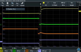
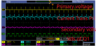
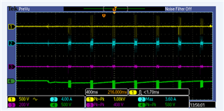
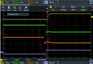
YELLOW: Voltage across primary winding
Blue: Primary Current
Purple: Voltage across secondary winding
Green: Vds of Q1 (Leg-1 top SiC)
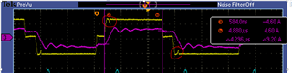
It seems to me that we are going out of control and peak current suddenly went up to 18A which is not obvious. However Q1 voltage looks ok and also bottom half of transformer voltage looks ok.
Top half side of the transformer voltage is completely destroyed. Also it is exactly the point where I think closed loop start regulating?
NB: Ignore the current direction on both the waveform it was just that current clamp meter was connected in different direction hence two current appearing out of phase. Just to avoid confusion.
Would appreciate your quick support on this.