This thread has been locked.

If you have a related question, please click the "Ask a related question" button in the top right corner. The newly created question will be automatically linked to this question.

LM3671: LM3671MF-ADJ Feedback voltage should be 0.5V, but is 0.61V

Part Number: LM3671

tl;dr: the feedback voltage on the LM3671MF-ADJ seems to be 0.62V, when the datasheet says it should be 0.5V

Longer version:

I'm using Table 3 on page 20 of this datasheet: https://www.ti.com/lit/ds/symlink/lm3671.pdf?ts=1655342005139

Desired Vout: 2.8V
Vin: 3.3-4.2V (LiPo cell)

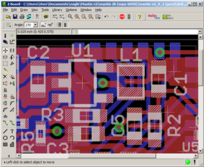
I'm using the resistor and capacitor values specified in the chart (464 & 100 kOhm, 8.2 and 33 pF), but instead of getting 2.8V, I'm getting 3.48V.  I have measured the feedback voltage as 6.2V, which contradicts the datasheet's specification of 0.5V.  I swapped out the 464kOhm resistor to a 360kOhm resistor, and got a Vout of 2.81V.  I replaced it with a 1kOhm resistor, and Vout dropped to 0.62V.  In all cases, Vfb stayed at 0.62V.  Nothing else is connected to Vfb's node.   I've tested this across three boards now, and I've run out of ideas.  I've attache screenshots of the relevant schematic and PCB layout (sorry if it's a bit messy).

Does anyone have any clue what might be going on?

  • Hello Ammon,

    Thanks for coming to us with your queries.

    The VFB is 0.5V and not 0.62V. However, I'm not sure if the issue is related to the IC sample or an external influence (ex. PCB layout) causing the Vout not to regulate properly.
    1. Can you send a waveform with Vin, FB, and VOUT on it?
    2. Did you try to replace LM3671? Is the Vout still regulating at 3.48V? Please send a waveform with Vin, FB, Vout as well.

    Best regards,

    Excel

  • I have attached waveforms of the three pins on the board where I replaced the 464 kOhm resistor with a 360kOhm resistor.  There's not much to see here--they're quite steady.

    Vin and Vout:

    Vin (yellow) and Vout (blue)

    And Vfb (note the scale difference):

    Vfb

    I have a few dozen of these boards, and have tested several.  They all have a Vout of 3.4V with the 464k and 100k resistors.

  • Hi Ammon,

    Thanks for the quick response.

    In the last waveform, the VFB is ~0.6V and not 0.5V, which it is suppose to be.

    Where are they bought the ICs? From TI store or Distributor?
    Can you check the body marking? And it should be "SBTB".

    If you can send a photo of the device that shows the body markings, it will be great.

    Best regards,

    Excel

  • I will follow up with our contract manufacturer to find out where they sourced the ICs.  The body marking is SBTB, as it should be.

  • Hello Ammon,

    Thank you for responding to my queries.

    Please see other suggestions below.
    1. Send a waveform with Vout and SW voltage. I want to ensure that the IC is still switching or not. If there is no switching event and VFB = ~0.6V, then an external voltage is biasing the output rail.

    2. Do you have an LM3671 evaluation board? You can place the IC on the board and check the output voltage and VFB. If the Vout is over the regulation and the FB voltage is ~0.6V, then there is an issue with the device. If not, there might be an issue with your PCB layout or circuit.

    3. The possible option is to contact our local TI Sales team or the Distributor that sold the parts to your contract manufacturer and send a few samples for failure analysis. The local FA team will assess if we need to be involved in determining the root cause of the issue or if they can resolve it within their team.

    I'm looking forward to your feedback.

    Best regards,

    Excel

  • I have heard back from our CM.  It appears that someone substituted a non-TI part, and did not adequately communicate what had happened.  So it isn't a fault with a TI part.  Thank you for your support!