This thread has been locked.

If you have a related question, please click the "Ask a related question" button in the top right corner. The newly created question will be automatically linked to this question.

LMS3655: Fly-Buck snubber options

Part Number: LMS3655
Other Parts Discussed in Thread: LM5017

Hello TI!

We are using LMS3655 in Fly-Buck configuration. Datasheet does not mention Fly-Buck configuration so i had to get inspired by other app notes.

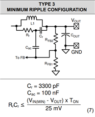
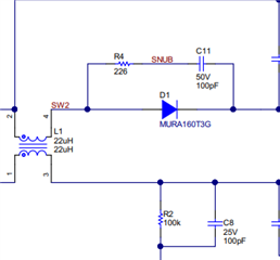
As i understand, there are two ways to implement snubbers - 1) Across primary windings and to FB via a cap, 2) Across output diode.

  •  How come these two documents only mention one of the options each and not both? Can they be used both at the same time?
  • Are there any other ways to reduce EMI? We dont care about efficiency, as long as EMI is low.
  • Should Cac be specifically 100n or should we try adjust it for the perfect value?

1) www.ti.com/.../lm5017.pdf

2) https://www.ti.com/lit/an/snva790a/snva790a.pdf?ts=1658652375816&ref_url=https%253A%252F%252Fwww.google.com%252F

Thank you,

Valentinas

  • Hi Valentinas,

    Yes you can use both snubbers. Conducted EMI is caused by high-frequency voltage and current spikes and ripple, the snubber on the primary will reduce the EMI conducted to the power supply, and a snubber on the secondary diode will reduce ripple on the fly-buck output.

    In addition to an EMI filter, ferrite beads and common mode chokes can help reduce very-high frequency EMI.

    An EMI shield would also be useful for if you're addressing radiated EMI. 

    Cac of 100nF is a good starting point. If your upper FB resistor is large >100kΩ, then the transient response may be slower and you can try to reduce Cac.

    Hope this helps,

    -Orlando

  • Hello Orlando,

    Thank you for your help.
    I was looking to increase the upper FB resistor but i am not sure how much higher i can go? The datasheet recommends 50k to ensure stability over all modes. If i only have 100mA load rather than 5A, does that mean i can easily increase this resistor? How do i know where the limit is?

    -Valentinas

  • Hi Valentinas,

    I just double-checked, LMS3655 is peak-current mode control, you should not use the type-3 ripple generation that is associated with Constant-ON time converters such as LM5017.

    Do not use a RC across the primary and no Cac is necessary. The output capacitance and the feedforward capacitor CFF are the design knob for these internally compensation peak-current mode control devices. Design the primary-side VOUT with capacitance as recommended in the datasheet or WEBENCH, and you can use the appnote below to fine-tine the CFF.

    https://www.ti.com/lit/an/slva289b/slva289b.pdf

    sorry for the confusion.

    -Orlando

  • Thank you Orlando, i will be trying CFF adjustments soon.
    I was also wondering about the sec output rectifying diode, from what i understood the reverse recovery time and capacitance are also causing EMI. I am confused though, should i be looking for diodes with the lowest reverse recovery time or the lowest capacitance?

  • Hi Valentinas,

    You should look for both, but probably prioritize low capacitance to minimize resonance with the leakage inductance of the winding.

    -Orlando