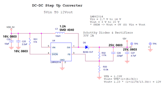
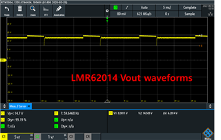
Using your LMR62014, we designed a circuit that boosts to 5V -> 12V.
It is designed in the same way as the connection plot on the two pages of the datasheet. (10uF added to input)
However, when the LED bars (Diode turn-on 3.7V, 250mA, two series) are connected and turned on, heat of more than 100 degrees toward the DCDC circuit is generated.
In the case of LEDs, an LED driver is used and PWM control is performed by receiving a 12V input.
I received a reply from the TI chat that there is nothing wrong with the circuit.
There seems to be a problem with the LMR62014 circuit currently designed because there is no problem with heating when outputting 12V by connecting the LMR62014 demo board to the PCB.
The reason is
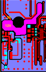
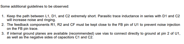
1. Artwork Problems
(5V, 12V adjacent to or different power lines)
2. Part selection problem (size, internal pressure, etc.)
Could you tell me why the heat is generated?
Also, I would like to know the difference from Demoboard Schematic, not Datasheet connectivity.