This thread has been locked.

If you have a related question, please click the "Ask a related question" button in the top right corner. The newly created question will be automatically linked to this question.

LM5022: How to change or increase the hysteresis of LM5022 UVLO ?

Part Number: LM5022

Hi team

There is a good new that we DIN LM5022!

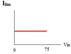
If the LM5022 wants to change or increase the hysteresis of UVLO, is there a suggested solution?

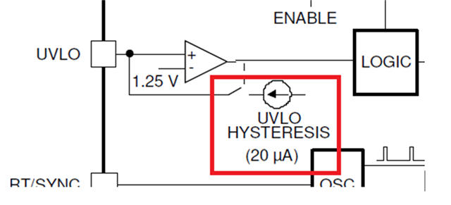
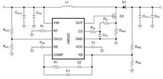
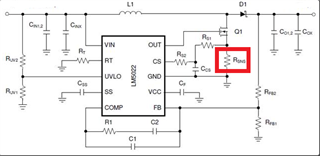
At present, the SPEC is using a 20-μA current source (red box below)
But how to design hysteresis with this current source?! Thanks

  • Hello Kygo,

    Thanks for promoting or products.

    The LM5022 UVLO shutdown threshold = 1.25V

    As per the example in the datasheet, where RUV1 = 2.61K and RUV2 = 10K:

    Minimum input voltage (rising), necessary to exceed the threshold on the UVLO pin = 6.04V

    When the UVLO threshold is exceeded (upwards), the current source is activated to instantly raise the voltage at the UVLO pin:
    The 20µA current creates an additional voltage drop of 20µA * 2.61K = 0.0522V on the low side resistor, so the level, that the UVLO pin sees, jumps up to 1.3022V
    20µA * 2.61K = 0.0522V hysteresis at the UVLO pin.

    The input now needs to drop down to 5.79V to bring the UVLO pin down to below 1.25V
    When the UVLO pin voltage falls below 1.25V the 20µA current source is turned off, causing the voltage at the UVLO pin to fall down to 1.198V

    The input voltage needs to rise up to 6.04V again to turn the LM5022 back on

    Hysteresis on the supply voltage = 0.25V
    When you increase the values of the divider resistors you will get a higher hysteresis.

    Best regards,
    Harry

  • Hi Harry 

    Thank you for the feedback!

    More question,

    The OCP function of LM5022 has no hiccup mode.
    Instead, the figure on the right outputs the drop voltage mode.

    Because the customer's input range is a bit large (9-75VDCin)... If customer want to design the OCP current protection point (Ilim) in the above picture to be as consistent as possible within the input range!!!!
    Can those components in the picture below be adjusted? THX

  • Hello Kygo,

    All components can be adjusted.

    In am not sure, if I understood what exactly the question is.

    Can you please explain in more detail?

    Thanks,

    Harry

  • Can I ask two questions?!Thanks!!

    <1>Minimum input voltage (rising), necessary to exceed the threshold on the UVLO pin = 6.04V

        =>How to get the value of 6.04V?

    <2>The input now needs to drop down to 5.79V to bring the UVLO pin down to below 1.25V

        =>How to get the value of 5.79V?

  • Hello Kygo,

    Just use Ohm's law for resistor dividers:
    VIN * RUV2 / (RUV1 + RUV2) = UVLO threshold
    Rising: 6.02V * 2.61K / (2.61K + 10K) = 1.25V
    Falling: 5.79V * 2.61K / (2.61K + 10K) = 1.198V ; 1.198V + 0.0522V [offset due to the 20µA current through RUV1] = 1.25V

    Regards,
    Harry

  • Hi Harry

    Thank you

    The figure of LM5022 OCP function 

    I want to improve as below:

    Can those components in the picture below be adjusted?

  • Hello Kygo,

    Where do you find the information for the blue curve?
    Please explain.

    The LM5022 can not regulate on average current (e.g. generating a fixed output current for charging a battery).
    The inner peak current mode control loop is meant to stabilize the output voltage, not the (average) output current.
    The Overcurrent protection should never be triggered, only tf a component breaks.
    The level of the OCP threshold cannot be modified independently

    Regards,
    Harry

  • Hi Harry

    Thank you

    <1>The OCP function of LM5022 occures output voltage drop?!

    <2>The Overcurrent protection should never be triggered, only tf a component breaks.

           Can you please explain in more detail ?!

  • Hello Kygo,

    I agree that my previous wording was misleading. Sorry for that.
    Let me try to explain in a more detail.

    During regular operation the inductor current should have a triangular waveform. Via the current sense resistor this signal is fed into the LM5022.
    Inside of the LM5022 the slope compensation ramp will be added on top of this measured signal. The resulting signal forms a ramp which is increasing during one cycle.
    Somewhere within this cycle the signal exceeds 0,5V and the FET gets turned off.
    For the rest of this cycle the inductor current will ramp down. At the beginning of the next cycle the FET will turn on again.

    The current sense resistor has to be calculated properly, so that this process can work as described above.

    Some kind of failure which could cause a permanent short / high currents right at the beginning of each and every cycle would be considered as an overcurrent.
    The driver will always turn off 65ns after the beginning of each cycle to protect the external FET.

    In case of a working system such high currents should only happen for a few cycles, in case of an immediate load change, but not permanently.

    Choosing a sense resistor that is too big will terminate the cycle too early which will result in some kind of current limiting mode where the controller has no chance to ever reach the configured output voltage.
    This is not a desired operating mode.

    Therefore, the current sense resistor has to be calculated properly, as per the description in the datasheet.

    Best regards,
    Harry

  • HELLO Harry

    Thanks for your support

    one more question

    The current sense resistor has to be calculated properly, so that this process can work as described above.

    =>"current sense resistor" refers to RSNS ?!