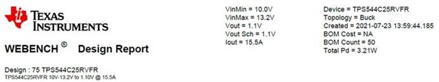
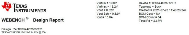
I use two TPS544C25RVFR DC-DC controllers on this design - one for 1.1V DDR5 VDD and one for 0.82V CXL controller Vcore. I used WBDesign online tools for these two circuit designs. They have similar circuit but different value for comments in FB, COMP and RT circuit due to loading and voltage different.
They have different usage for Vset per WBDesign online tools generated circuit:
- Vset is used for 1.1V DDR5 VDD – Rbootup = 133K 1%
- Vset is not used for 0.82V CXL controller Vcore – it is pulled up to V_BP3.
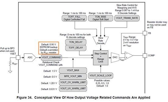
Per TPS544C25RVFR DS, the power-on/reset Vout is set either by Rset when VSET is used or by EEPROM when VSET is not used.
Question:
1, For VSET is not used applications, does Ti have tools for EEPROM ISP programming? Does Ti have pre-programming service for out mass production?
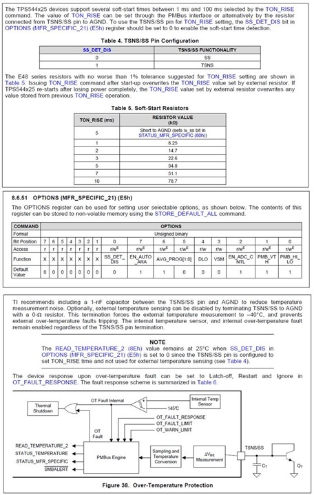
2, For Rset value when VSET is used, are following VOUT values only supported options for boot-up? If not, what Rset value can set Vout to 0.82V?
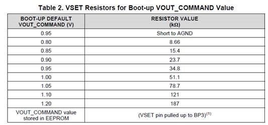
3, Per above table, for 1.10V Vout, the Rset should be 121K 1%, why the WBDesign tools generated schematics and BOM use 133K 1%?
Thanks!