Hi team,
My customer uses LM5030 in their project(Vin=48V, Vout=210V/1A), could you please help check below questions?
1. What is the operating mode of the LM5030 at light load (or no load), is it a hiccup mode?
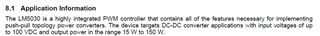
2. The power range recommended on the datasheet is 15W to 150W, is there a risk if the power is 210W?
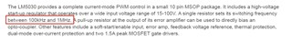
3.SNVA548 this document recommends frequencies from 100K to 1M. Can they set the frequencies to 65KHz?
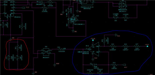
4. Could you please help review the feedback loop's schematic?
Appreciate for your help!

Regards,
Ivy