This thread has been locked.

If you have a related question, please click the "Ask a related question" button in the top right corner. The newly created question will be automatically linked to this question.

BQ27421-G1: BQ27421-G1A

Part Number: BQ27421-G1


After programming a golden gauge file, I run three charge discharge cycles on the single cell 21700 battery in application

xp223600015_Battery_Log.csv

The Design capacity is 3600mAh

The termination voltage in golden gauge file is set to 3150mV, Residual capacity is 100mAhours .

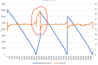
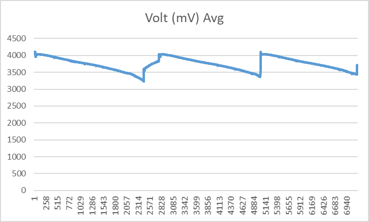
For the First guage correctly guages the SOC and sets it to 0% when voltage is close to 3200mV. On the second and third cycles, the voltage at which SOC is set to 0% drifts upwards to 3300mV and 3450mV respectively. THis is affecting run time of device.

I expect the end voltage to be ~3200mV due to the termination voltage setting in the battery.

THe discharge load is constant power of approximately 1.6W. Charging current is 1A.

What could be causing this drift?

xp223600015_Battery_Log.csv

  •  Parameter name  Parameter Value  Display Units
    Over Temp 55 °C
    Under Temp 0 °C
    Temp Hys 5 °C
    TCA Set % 99 %
    TCA Clear % 95 %
    FC Set % -1 %
    FC Clear % 98 %
    DODatEOC Delta T 5 °C
    Design Voltage 3600 mV
    Initial Standby -3 mA
    Initial MaxLoad -200 mA
    SOC1 Set Threshold 10 %
    SOC1 Clear Threshold 15 %
    SOCF Set Threshold 2 %
    SOCF Clear Threshold 5 %
    OpConfig 25f8 Flag
    OpConfigB 0f Flag
    Hibernate I 3 mA
    Hibernate V 2200 mV
    FH Setting 0 60 s
    Ra Filter 800 Num
    FH Setting 1 100 s
    FH Setting 2 18000 s
    FH Setting 3 25 s
    Fast Qmax Start DOD % 92 %
    Fast Qmax End DOD % 96 %
    Fast Qmax Start Volt Delta 125 mV
    Fast Qmax Current Threshold 4 Hr rate
    Fast Qmax Min Points 3 Num
    Max Qmax Change 20 %
    Qmax Max Delta % 10 %DCap
    Max % Default Qmax 120 %DCap
    Qmax Filter 96 Num
    ResRelax Time 500 s
    User Rate-mA 0 mA
    User Rate-mW 0 mW
    Max Sim Rate 1 Hr rate
    Min Sim Rate 20 Hr rate
    Ra Max Delta 11 4mOhm
    Min Delta Voltage 0 mV
    Max Delta Voltage 0 mV
    DeltaV Max dV 100 mV
    TermV Valid t 2 s
    Dsg Current Threshold 250 .1 Hr rate
    Chg Current Threshold 250 .1 Hr rate
    Quit Current 430 .1 Hr rate
    Dsg Relax Time 60 s
    Chg Relax Time 60 s
    Quit Relax Time 1 s
    Max IR Correct 400 mV
    Qmax Cell 0 19569 Num
    Update Status 0 Hex
    Reserve Cap-mAh 100 mAh
    Load Select/Mode 81 Hex
    Q Invalid MaxV 3803 mV
    Q Invalid MinV 3752 mV
    Design Capacity 3600 mAh
    Design Energy 12960 mWh
    Terminate Voltage 3150 mV
    T Rise 20 Num
    T Time Constant 1000 s
    SOCI Delta 1 %
    Taper Rate 230 .1 Hr rate
    Taper Voltage 4050 mV
    Sleep Current 10 mA
    V at Chg Term 4100 mV
    Avg I Last Run -71 .1 Hr rate
    Avg P Last Run -70 .1 Hr rate
    Delta Voltage 1 mV
    R_a0 0 102 Num
    R_a0 1 102 Num
    R_a0 2 99 Num
    R_a0 3 107 Num
    R_a0 4 72 Num
    R_a0 5 59 Num
    R_a0 6 62 Num
    R_a0 7 63 Num
    R_a0 8 53 Num
    R_a0 9 47 Num
    R_a0 10 60 Num
    R_a0 11 70 Num
    R_a0 12 140 Num
    R_a0 13 369 Num
    R_a0 14 588 Num
    Board Offset 0 Counts
    Int Temp Offset 0 °C
    Pack V Offset 0 mV
    CC Offset -16 Counts
    CC Cal Temp 302.3 °K
    CC Gain 0.3448 Num
    CC Delta 411356.2188 Num
    Deadband 5 mA
  • Hello,

    There's a big change in temperature, please see below. 


    This gauge uses impedance track algorithm. This algorithm takes three periodic measurements (current, voltage, and temperature) to predict RM, FCC, SOC, etc. When there's a change in temperature greater than 5C, this causes the gauge to report less capacity, hence the terminate voltage will be reached faster.

    Did you do voltage calibration on the new board? The board might have offsets causing Terminate Voltage to reach earlier.
    Have you tried other load selects? I would suggest you try different load selects. Have you tried constant current mode? This is the most typical.

    Please provide the configuration gg file, so that I can run simulations and help you better.

    Regards,
    Jose Couso 

  • Golden Image_09192022.gm.fs.txt
    ;--------------------------------------------------------
    ;Verify Existing Firmware Version
    ;--------------------------------------------------------
    W: AA 00 01 00
    C: AA 00 21 04
    W: AA 00 02 00
    C: AA 00 09 01
    ;--------------------------------------------------------
    ;SET_CFGUPDATE
    ;--------------------------------------------------------
    W: AA 00 13 00
    X: 1100
    ;--------------------------------------------------------
    ;Data Block
    ;--------------------------------------------------------
    W: AA 3E 02 00
    W: AA 40 02 26 00 00 32 00 00 00 00 00 00 00 00 00 00 00 00 00 00 00 00 00 00 00 00 00 00 00 00 00 00 00
    W: AA 60 A5
    X: 10
    W: AA 3E 02 00
    C: AA 60 A5
    W: AA 3E 24 00
    W: AA 40 00 19 28 63 5F FF 62 00 32 00 00 00 00 00 00 00 00 00 00 00 00 00 00 00 00 00 00 00 00 00 00 00
    W: AA 60 69
    X: 10
    W: AA 3E 24 00
    C: AA 60 69
    W: AA 3E 30 00
    W: AA 40 0E 10 FD FF 38 00 00 00 00 00 00 00 00 00 00 00 00 00 00 00 00 00 00 00 00 00 00 00 00 00 00 00
    W: AA 60 AD
    X: 10
    W: AA 3E 30 00
    C: AA 60 AD
    W: AA 3E 31 00
    W: AA 40 0A 0F 02 05 32 00 00 00 00 00 00 00 00 00 00 00 00 00 00 00 00 00 00 00 00 00 00 00 00 00 00 00
    W: AA 60 AD
    X: 10
    W: AA 3E 31 00
    C: AA 60 AD
    W: AA 3E 40 00
    W: AA 40 25 F8 0F 00 00 14 04 00 09 00 00 00 00 00 00 00 00 00 00 00 00 00 00 00 00 00 00 00 00 00 00 00
    W: AA 60 B2
    X: 10
    W: AA 3E 40 00
    C: AA 60 B2
    W: AA 3E 44 00
    W: AA 40 05 00 32 01 C2 14 14 00 03 08 98 01 00 00 00 00 00 00 00 00 00 00 00 00 00 00 00 00 00 00 00 00
    W: AA 60 39
    X: 10
    W: AA 3E 44 00
    C: AA 60 39
    W: AA 3E 50 00
    W: AA 40 02 BC 01 2C 00 1E 00 C8 C8 14 08 00 3C 0E 10 00 0A 46 05 14 05 0F 03 20 00 64 46 50 0A 01 90 00
    W: AA 60 BB
    X: 10
    W: AA 3E 50 00
    C: AA 60 BB
    W: AA 3E 50 01
    W: AA 40 64 19 DC 5C 60 00 7D 00 04 03 19 25 0F 14 0A 78 60 28 01 F4 00 00 00 00 00 00 43 80 04 01 14 00
    W: AA 60 2A
    X: 10
    W: AA 3E 50 01
    C: AA 60 2A
    W: AA 3E 50 02
    W: AA 40 0B 0B B8 01 2C 0A 01 0A 00 00 00 00 00 64 02 00 00 00 00 00 00 00 00 00 00 00 00 00 00 00 00 00
    W: AA 60 89
    X: 10
    W: AA 3E 50 02
    C: AA 60 89
    W: AA 3E 51 00
    W: AA 40 00 FA 00 FA 01 AE 00 3C 3C 01 B3 B3 01 90 00 00 00 00 00 00 00 00 00 00 00 00 00 00 00 00 00 00
    W: AA 60 EC
    X: 10
    W: AA 3E 51 00
    C: AA 60 EC
    W: AA 3E 52 00
    W: AA 40 4C 71 00 00 64 81 0E DB 0E A8 0E 10 32 A0 05 3C 0C 4E 00 C8 00 32 00 14 03 E8 01 00 E6 0F D2 00
    W: AA 60 72
    X: 10
    W: AA 3E 52 00
    C: AA 60 72
    W: AA 3E 52 01
    W: AA 40 0A 10 04 FF B9 FF BA 00 01 02 BC 00 00 00 00 00 00 00 00 00 00 00 00 00 00 00 00 00 00 00 00 00
    W: AA 60 B1
    X: 10
    W: AA 3E 52 01
    C: AA 60 B1
    W: AA 3E 59 00
    W: AA 40 00 66 00 66 00 63 00 6B 00 48 00 3B 00 3E 00 3F 00 35 00 2F 00 3C 00 46 00 8C 01 71 02 4C 00 00
    W: AA 60 33
    X: 10
    W: AA 3E 59 00
    C: AA 60 33
    W: AA 3E 70 00
    W: AA 40 80 00 80 00 00 00 00 00 00 00 00 00 00 00 00 00 00 00 00 00 00 00 00 00 00 00 00 00 00 00 00 00
    W: AA 60 FF
    X: 10
    W: AA 3E 70 00
    C: AA 60 FF
    ;--------------------------------------------------------
    ;Exit CFGUPDATE
    ;--------------------------------------------------------
    W: AA 00 00 00
    W: AA 00 42 00
    X: 2000
    

    Thank you for the observation on the temperature. The golden gauge image and the configuration gg files are attached here, Please use these for simulations.

    I did not do voltage calibration on the new board. From the voltage readings in the log file, the fully charged voltage is what I expect from the charger, so I don't expect a significant voltage offset.

    I have tried load mode 81. I will try load mode 82.  

    Our application is a constant power mode load. Therefore I have not tried constant current mode.

    9_19_2022_gg.csv

  • Hello,

    Thanks for the gg file. I will take a look as soon as I can and get back to you. 

    Regards,
    Jose Couso

  • Hello,

    I was looking at the gg file and Design Voltage is set to 3600 mV, but the log file shows that the maximum voltage charge is 4105 mV. This causes gauging issues because the gauge is being told to say 100% RSOC when voltage is 3600 mV, and then voltage keeps increasing to 4105 mV. I suggest you stop charging at design voltage parameter.


    Also, I recommend you use the quick start guide for the bq27421 (especially chapter 4 - Programming Configuration). Please see below.

    https://www.ti.com/lit/ml/sluuah7b/sluuah7b.pdf?ts=1664292340238&ref_url=https%253A%252F%252Fwww.ti.com%252Fproduct%252FBQ27421-G1


    Regards,
    Jose Couso