This thread has been locked.

If you have a related question, please click the "Ask a related question" button in the top right corner. The newly created question will be automatically linked to this question.

TPS65261: Understanding pull-up currents for external cap CEN

Part Number: TPS65261

Hello,

The startup characteristic using an external capacitor on the enable pins seems well defined based on the internal current sources. My question pertains to the source of the pull-up currents. In the block diagram there is a 3.6uA and 3uA source as well as a 1.2V reference. In another post I read that the currents are supplied from the V7V regulator.

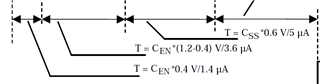
Where is the '1.4uA' source listed in figure 28 is from? Similarly, where is the threshold of 0.4V from, before the 3.6uA pull-up current is enabled?

Thank you,

Michael Rosa

  • Hi Michael,

    Due to National Day holiday, the China team (who work on this device) will give you response by 10/8.


  • Hi Michael,

    Thanks for reaching out! 

    A typical 1.4-µA current is charging ENx pin from input supply. When ENx pin voltage rise to typical 0.4 V, the internal V7V LDO turns on. A 3.6-µA pullup current is sourcing ENx. After ENx pin voltage reaches to ENx enabling threshold, 3-µA hysteresis current sources to the pin to improve noise sensitivity.

    Hope this helpful. Anything unclear, kindly let me know! Thanks!

    BRs

    Lucia

  • Hi Machael,

    I also noticed your email about TPS65261 schematic review. Let's talk by email. I will close this thread first.

    Thanks!

    BRs

    Lucia