This thread has been locked.

If you have a related question, please click the "Ask a related question" button in the top right corner. The newly created question will be automatically linked to this question.

BQ76942: Create a 'System present' function using TS2 and RST_Shut

Part Number: BQ76942

Can I connect the RST_SHUT to TS2 to create a 'system present' function. I'm thinking that when RST_SHUT is high, the device should enter shutdown, then when the line is taken low, TS2 will go low and cause the device to wake up. Will this work or is there a better way to create a single line / shutdown/wake up function?

  • Hello Richard,

    This particular configuration may not work due to the way the device and these pins works. The SHUTDOWN function was intended to only be entered when the long-term storage of a battery. If these were directly shorted together, you'd need to externally pull the pin high to shut the device off. And externally short TS2 to Vss to wake the device. Once the device is ON, TS2 will by default function as a thermistor, which pulses periodically, this could potentially make the part go into a constant reset.

    We've never done a configuration like this before.

    However, he is an idea that maybe would work. Keep in mind that this has not been tested and there could be issues we have not foreseen:

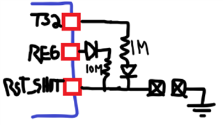
    Let's assume the device with the above configuration is initially ON. In this case the GND connection is connected to RST_SHUT, keeping it low and the device ON.

    Now we disconnect the GND from these pins, once this is disconnected from the system, the RST_SHUT pin is left floating and will be pulled high through the 10-MOhm resistor to the REG voltage. This would shut-down the IC as now RST_SHUT will be high.

    Similarly, let's assume the device is initially OFF and the GND is disconnected. In this state TS2 is floating and internally pulled high to ~5.5-V in a Hi-Z state. 

    Now we connect the GND to these pins, which would pull the TS2 pin low through the 1-MOhm resistance, waking the device. The diodes in the REG and TS2 is to avoid any voltages to leak between the REG and TS2 voltages when the device is transitioning to turn OFF after the GND connection is removed.

    We have not tested this and I am not entirely sure if it would work. You could potentially try to characterize its behavior and see if would work for your system present function.

    Best Regards,

    Luis Hernandez Salomon

  • Nice work ! - It seems to work. The only difficulty is that this only works when the device has been programmed with OTP. without programing, the device reboots, turns off Vreg and returns the registers to default values. So it won't work twice. Once programmed however, it seems to work.

  • Glad that it worked!

    That sounds about right, if you choose a device that does not have REG1 enabled you would have to OTP a REG to turn ON by default in order to make this configuration work. As the device will always start with its default values after SHUTDOWN.

    Let us know if you have any further questions!

    Best Regards,

    Luis Hernandez Salomon