A related question is a question created from another question. When the related question is created, it will be automatically linked to the original question.
If you have a related question, please click the "Ask a related question" button in the top right corner. The newly created question will be automatically linked to this question.
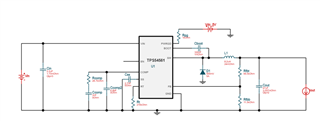
for a simple rule of thumb approach, I suggest the following. Where Lbuck is the buck inductor, Lf is the filter inductor, Cout is the output capacitor for the buck power stage and Cf is the filter capacitor. Make Lf<<Lbuck and Make Cout <<Cf. Suggest Lf and Cout are an order of magnitude leass than Lbuck and Cf respectively.
Also note that the ESR of Cf will need to be equal to approximately Sqrt(Lf/Cf).
Therefore suggest the following with the example shown above. Make Lf = 100nH, make Cf = 470uF, ESR~15mR.