Hi Expert,
Lately I am reading Adjustable Current Limit of Smart Power Switches (Rev. B) and I have several questions.
- the app note mention that there are several current mirror architecture in TI high side switches. But it only shows one solution in the app note. May you help share other current mirror architecture? Thanks.
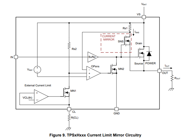
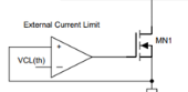
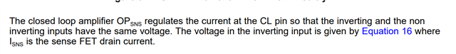
For the current mirror architecture, I also have some question. In the app note, it describe as below, "The closed loop amplifier OPSNS regulates the current at the CL pin so that the inverting and the non inverting inputs have the same voltage." It seems strange to me that e current at the CL pin is constant, it equals VCL(th)/RCL. Why it can be regulated?
From my understanding, OPsns outputs low when normal working and output high when overcurrent happens. Is it correct? And The voltage on OPsns "+" and "-" pins are not equal, right? Actually if you can detailed explain how OPsns works to limit the current, that will be perfect. Thanks.
BR,
Elec Cheng