This thread has been locked.

If you have a related question, please click the "Ask a related question" button in the top right corner. The newly created question will be automatically linked to this question.

TLC5928: device changes output by itself ?

Part Number: TLC5928

Hi.

We are using a TLC5928 chip in a card reader application, to control 2 groups of RGB LEDs.
Each group of RGB LEDs is using 3 output pins of the TLC5928 chip, one pin per color.

schematics picture

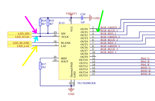
Schematics show more outputs in use, but they are actually RFU and not connected.
RGB LEDs cathodes are connected to OUT0, OUT1 and OUT2 through some little resistors (~ 68 ohms)
RGB LEDs anodes are connected to VDD3V3.

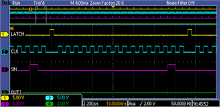
To have more than 8 colors per group, some hardware is constantly updating the chip output
by clocking 16 bits of data, latching, clocking again 16 bits of data, latching, and so on.
Frequency is not very high, a new 16 bits value is latched every 1.3 millisecond.
SCLK frequency is around 13.9 kHz :

We are facing a strange chip behavior.
When we try to change RGB LEDs color and therefore switch from state { OUT0 active, OUT1 active, OUT2 inactive } to state { OUT0 inactive, OUT1 active, OUT2 inactive },
then the chip is shutting down all its output !

Here is this situation :

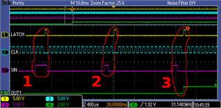
In <1>, last two bits of clocked value are both 1, asking for OUT1 active and OUT0 active.
After the latch pulse, green signal (OUT1) is still low = active as expected.

Then a color change occurs and a new 16-bits value is clocked.
For this new color, I need to have OUT0 disabled, and keep OUT1 enabled.
In <2>, last two bits of clocked value are 1 and 0, asking for OUT1 active and OUT0 inactive.
OUT1 is kept active as expected, and OUT0 went probably inactive (OUT0 not present on my screenshot).

In <3>, same 16-bits value is clocked to the chip as in <2> : last two bits of clocked value are 1 and 0, asking again for OUT1 active and OUT0 inactive (no change).
But for some unknown reason, OUT1 goes high (disabled) and also all other outputs !

I closely read chip datasheet, and I think all timings are respected.
The hardware that generate signals SIN and CLK updates SIN during the falling edge of CLK and keep it stable during the next rising edge of CLK.
Also CLK is kept low during the LATCH pulse.

As I said, timings are quiet slow : rising edge of CLK occurs ~ 36 microseconds after SIN being updated, which is much more than the requested values
in the datasheet.

I know that the internal on/off control shift register of the chip is replaced by LOD / PTW diagnostic bits on the rising edge of LATCH,
but I'm always latching only once, and there are always 16 CLK before the next latch pulse.
So I think I'm not having the bad situation were LOD /PTW diagnostic bits would be latched by error to the on/off control data register.

There is absolutely no way to recover from this situation, whatever value is clocked & latched into the chip.
Only a power-off and power-on can have the chip perform again normally.
Chip temperature is probably not involved. Tested with freezer spray : no change.
Project can run for for hours with no problems, and issue occurs only on some color transitions (not all transistions).
Also note that BLANK pin is unused and kept low.

Any help / hint would be greatly appreciated !

Best regards,

Fabrice GIRARDOT / DDM Hopt + Schuler / Germany

  • Hi Fabrice,

    1. Regarding your schematic, I am not sure why you use pull-up resistor for SCLK and SIN pin. Does the controller output pin is open-drain?

    2. How do you keep the BLANK pin low? By controller? Or by pull-down resistor? Or...?

    Also note that BLANK pin is unused and kept low.

    3. Can you specify what transitions (which channel) will trigger this behavior?

    Project can run for for hours with no problems, and issue occurs only on some color transitions (not all transistions).

    4. Could you try only initializing the controller (keep the TLC5928 power on) and restarting the clock and data transfer?

    There is absolutely no way to recover from this situation, whatever value is clocked & latched into the chip.
    Only a power-off and power-on can have the chip perform again normally.

    The behavior is really weird. I may need more detailed information to perform a deep-dive debug. 

    Best Regards,

    Steven

  • Hi Steven.

    Thanks for your reply.

    1. Controller output pins are push - pull, so I agree that those two pull-up resistors are useless.
    I'll ask the schematics author to remove them, or at least production team not to fit them on the boards.

    2. BLANK pin is kept low by controller. I already checked with oscilloscope that this pin is not set high by mistake.
    When the problem occurs, I also tried to manually toggle BLANK pin (low -> high -> low)  -> no change.

    3. The transition described in my first message does trigger every time the problem.
    Transition is from 0x0003 to 0x0002 (disabling OUT0 while keeping OUT1 enabled).
    Controller clocks 0x0003 and latches => OUT0 and OUT1 are enabled as expected, all other outputs disabled as expected.
    Then a LED color change is requested, and controller now needs to disable OUT0 to handle that color change.
    So now controller clocks new value 0x0002 and latches ; OUT1 is kept enabled as expected ; OUT0 is not monitored by oscilloscope, but is probably disabled as expected
    1.3 ms later, controller clocks again 0x0002 and latches.
    No output change is expected because that value was already latched just before.
    But oscilloscope shows that OUT1 goes disabled for no reason, while latched value 0x0002 did require to keep it enabled.

    4. I did already try to reset and fully re-init controller. No change.

    Please feel free to ask more details / explanations.

    Best regards,

    Fabrice

  • Hi Fabrice,

    The transition described in my first message does trigger every time the problem.
    Transition is from 0x0003 to 0x0002 (disabling OUT0 while keeping OUT1 enabled).

    Do you mean that this weird behavior occurs every time 0x0003 --> 0x0002 --> 0x0002 happens, no matter how long the device has run?

    Best Regards,

    Steven

  • Steven Li said:

    Do you mean that this weird behavior occurs every time 0x0003 --> 0x0002 --> 0x0002 happens, no matter how long the device has run?

    That's correct.

    Best regards,

    Fabrice

  • Hi Fabrice,

    Will the same thing happen when 

    1. 0x0002 --> 0x0002
    2. 0x0001 --> 0x0000-->0x0000-->0x0002. Can the channel1 turn on as expected?
    3. 0x0007--> 0x0006 --> 0x0006

    Also, does this thing happen to this single chip? Or multiple chips? 

    Best Regards,

    Steven