- Ask a related questionWhat is a related question?A related question is a question created from another question. When the related question is created, it will be automatically linked to the original question.
This thread has been locked.
If you have a related question, please click the "Ask a related question" button in the top right corner. The newly created question will be automatically linked to this question.
Hello!
Does anyone have sugestions for appropriate ways to provide constant charge/discharge current for performing the Learning Cycle?
I've seen this on the LM317L datasheet:
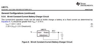
But it only provides 50mA. The LM317L's maximum capacity is 100mA. However, the TI's Learning Cycle manual says:

So 50mA should be good for any battery I'd guess, though C/2 is recommended.
But anyone have suggestions for this?
And for discharging, can it be as simple as a BJT transistor doing it's Ic=B*Ib?
Thanks in advance!
Hello Shirish,
For charge termination I assume you're referring to the green part of the Learning Cycle on this graph, right?
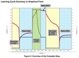
If so, for this battery, I should simply perform the green part following the battery's datasheet parameters for charging:
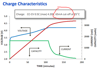
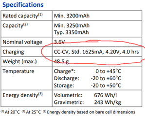
Charge using a constant current of 1625mA, constant voltage of 4.2V, and leave charging until the charge current drops down to 65mA, right?
Thanks again!
Ed
Hello Ed,
Yes. The current should drop down to below taper current for taper time duration, not necessarily a 65mA cutoff
Hello Shirish,
Now for charging, my battery circuit already uses one of the ICs of the link you gave. Its the BQ25883 (I2C 2 cell 2A Boost battery charger for USB input). This is the circuit:
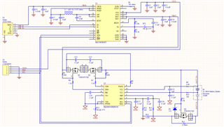
So can I perform the Charge Termination (green part) of the Learning Cycle using this charger that's already on my circuit? Note that my battery circuit uses 2 batteries.
Thanks Shirish, I'll do this then: Perform the Charge Termination part using the BQ25883 charger IC that's already on my circuit shown above.
Now, for both discharge parts (initial discharge and the discharge with I > C/10), I assume it must be done using an external load.
I see on the Learning Cycle PDF:

But it's not clear to me if there are ways to do this using the charger or gauge ICs, without an external load.
So, to confirm:
I must perform both discharge parts of the Learning Cycle by draining a constant current from the batteries, and drain this current through the charger and the gauge ICs, like a normal load attached to my battery manager circuit, right?
(I understand this current needs to be drained only through the gauge IC for the Learning Cycle, but the charger IC is between the gauge and the load output of the circuit)
No, but I can make a cut on the PACK+ trace that goes to the BAT pin of the charger, and place the load there for the discharge parts. Then jump it back for the charge part, if that's an option.
Hello Eduardo,
I would recommend connecting the load and charger to Pack+ / Pack-. There is no need to cut the trace
Yes, I'll do that then. I found a way to disable charging on my charger IC. So I'll disable charging for all stages of the Learning Cycle except "charge termination".
Now, my charger IC has a trickle-charge and pre-charge steps before the normal charging step.
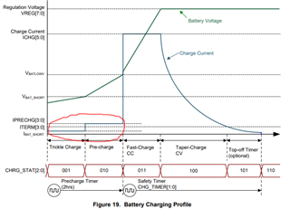
Can I still do the "charge termination" stage of the Learning Cycle with trickle charge and pre-charge before the normal charging?
You may need to trickle and pre-charge the battery if the voltage is below operating range. When we say fully discharge the battery, it means discharging completely to the point recommended by the battery manufacturer in the normal operating range.