Other Parts Discussed in Thread: LM5013
I'm having issues with a 12V power supply I designed.
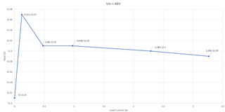
For testing I've got Vin set to 49V and with no load; I'm getting ~12.3V out. With a 1A load; I get 13V out. Also, the output voltage under load seems to be tied to the input voltage, because if I change my input voltage from 49V to 57V, the output voltage goes up to 13.1V.
I have a feeling my issue is with the Type 3 ripple generation circuit, because when I remove this circuit, the output voltage stays constant at the 12.2V that it is supposed to be, but it is also pretty noisy (over 600mV of RMS ripple voltage at the output).
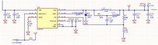
Here is the schematic for my circuit:
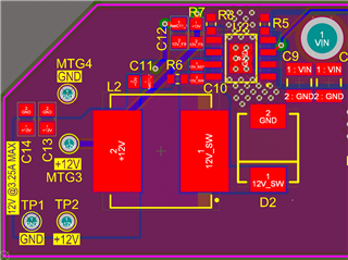
Here's the layout:
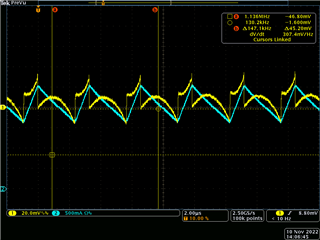
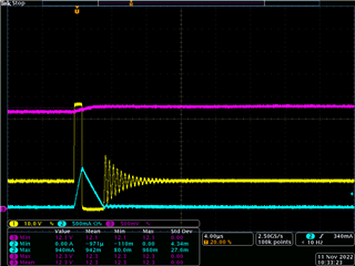
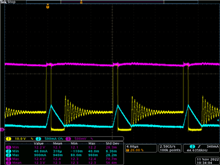
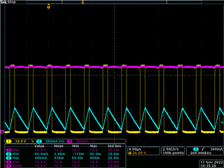
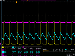
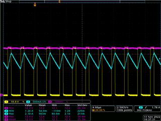
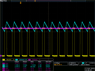
Here's the waveform of the inductor current (blue) and switch-node voltage (yellow):
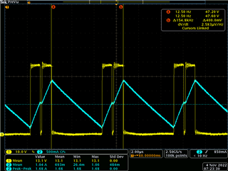
A few things I'm unsure about from the waveforms:
1. What could be causing the controller to turn off the in the middle there?
2. It looks like the frequency is actually 155kHz, even though the resistor setting should have it at 300kHz, am I looking at the waveform wrong?
- to get 300kHz, I used the equation, fsw = (12(V)*2500)/(100(kΩ)) = 300(kHz)
Is there something obvious that I'm missing with my design?