This thread has been locked.

If you have a related question, please click the "Ask a related question" button in the top right corner. The newly created question will be automatically linked to this question.

TPS40211: Hissing Noise of the Boost Converter

Part Number: TPS40211

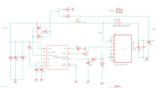
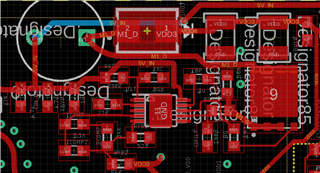
I have a 5volts to 30Volts Boost converter design. Using TPS 40211 DGQR Chip. I designed to output at 30Volts DC with max output current to be 200mA. When I start the circuit, the converter makes the hissing noise, and I think this may be adding some fluctuation to the circuit. I read from the forum saying that this may be a from an inductor and capacitor. I used the TI design tool, and I made sure that all my components are within the spec range. Could this hissing noise coming from the fact that my circuit is drawing more current than it was designed to be? I am not sure what is the cause of this issue. I am using 30Volts DCDC converter to power THS 3092 chip to generate 18.72Meg sinusoidal(18voltsp2p) to deliver this wave to the coil. I replaced 4.7uF with the 10uF 63Volts rated big capacitor(1205) size to the input of the converter to remedy this issue, but it wasn't helpful at all. I am attaching this Schematic and the PCB board layout. Any help would be greatly appreciated. I don't get hissing noise when the 30Volts is not connected to the opamp. It just happens when the circuit is turning on, and sometimes it goes away, and some times it comes back. I think that this is causing the circuit to have. unstable results.

Thank you so much

  • Hi Young,

    thank you for using the E2E forum.

    Investigating on this would require to measure deeper into the circuit to better see and understand where this noise is coming from.

    Typically, there are some oscillations which you can see on a scope.

    In general, if you load the DCDC with higher current then it was designed for this can happen, e.g. due to inductor getting into saturation.

    Also from your layout it looks like the current loop (input cap - inductor - MOSFET - current sense resistor) is really large and covering your whole power stage.
    This can also impact the stability.

    Is your Power pad (Thermal Pad) connected to GND. Schematic shows yes but could not see it in the layout.

    Can you check your output caps ? Are this ceramic Caps? If yes, check the DC BIAS of them. 

    Best regards,

     Stefan

  • Hi Young,

    as we have not received an additional information, I assume this issue is solved and I am closing the thread.
    If there is still something open, just reply to open it again or open a new thread.

    Best regards,
    Stefan