This thread has been locked.

If you have a related question, please click the "Ask a related question" button in the top right corner. The newly created question will be automatically linked to this question.

UCC2818A-Q1: supply from boost inductor auxiliary winding

Part Number: UCC2818A-Q1
Other Parts Discussed in Thread: UCC2818A, UCC2818

Hi again,

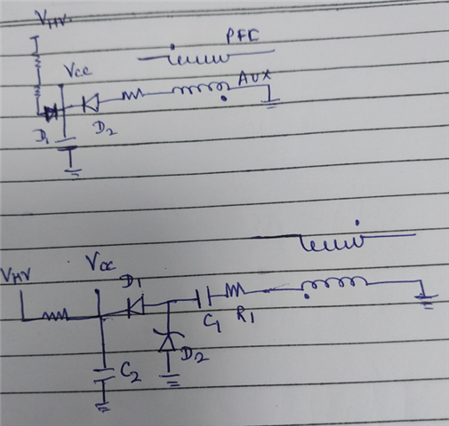
I tried to supply the IC with a solution similar to the one at pag.11 of the UCC2818A-Q1 datasheet: startup resistors + auxiliary winding on the boost inductor.

The differences from my circuit and the one at pag.11 are:

1) I used a half-wave rectifier (diode + cap 1uF) instead of a voltage doubler.

2) I placed a 15V zener diode after the 100R resistor because I'm not sure the UCC2818A has one inside.

Result: the IC is supplied and the boost converter works, but I made some measures and seems that half of the supply current flows on the startup resistors even after the startup.

I didn't find any application note about the design of this supply circuit, could someone help me?

Regards,

Marco

  • Hi Marco,

    Thank you for the query on UCC2818.

    You are correct in using a half wave rectifier with a zener similar to what we use for a bias supply from the auxiliary winding of the transformer.

    The following circuits can help with the current flow through the startup resistors.

    In the first circuit you can add a diode in series to prevent this power dissipation on the startup resistors.

    In the second circuit, during the positve voltage on aux winding, C1 is charged through R1 and the charge current will also charge C2 through D1.  At the same time, the Zener diode, D2, can avoid having too much charge voltage. When the auxiliary winding voltage is negative, C1 will be discharged through R1 and D2. D1 is reverse blocked.

    Page-5 of the following app note shows an example implementation.

    https://www.infineon.com/dgdl/Infineon-aneval_201511_pl16_012-AN-v02_00-EN.pdf?fileId=5546d462533600a40153559ff7761263

    Regards,

    Harish