Other Parts Discussed in Thread: PMP20873, UCC28070, UCC28180, LM5122,
Hi
This is a follow-up question regarding my first attempt to get power from a 3 phase PMSG to a grid-tied solar inverter. The first question is posted here: e2e.ti.com/.../lm5122-bode-plot-in-manual-possible-mixup-with-frequency-and-rad-s-where-does-an-output-lc-filter-come-in-the-tf-feedforward-of-rectifier-ripple-additional-risk-of-floating-ground-plane
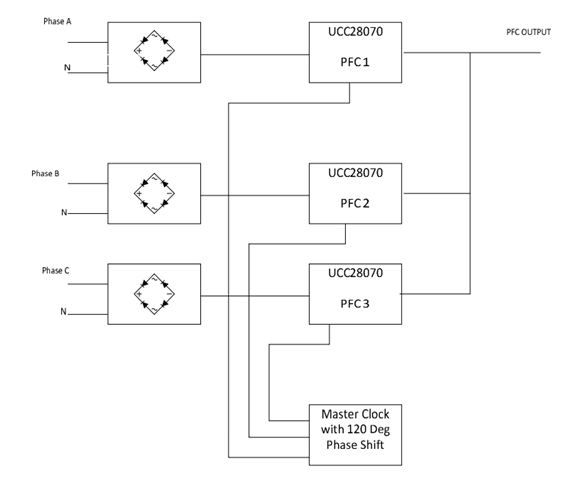
To recap: for this application (a water turbine) I'm trying to convert the energy of of a 3 phase 48VAC PMSG to a stable 80V output with minimal ripple that can be delivered to an off the shelf solar grid-tied inverter (max input 600VDC, minimum input = 70V).
So Brigitte suggested that maybe a PFC would be a better solution for this setup. After looking at these seminars: https://training.ti.com/power-factor-correction-pfc-circuit-basics and this seminar: https://training.ti.com/choosing-right-pfc-topology-100w-several-kw I can only agree with Brigitte's suggestion.
I'm having some trouble with determining which chip I should use.
Here are the design considerations:
- Space: isn't that important there is plenty of room
- EMI on the generator side isn't that important. Off course On the DC side we want a quite clean signal and there are other electronics on the board so it shouldn't interfere with these.
- Efficiency and cost are equally important. But I rather spend more money on silicon than on aluminium, with which I mean that a high efficiency design with smaller heatsinks are prefered over lower efficiency and larger heatsinks
- not too much complexity
- Power: currently 500W, but for the future up to 2kW. The 2kW will be with another generator with higher voltages, but also 3 phase.
Questions:
- Most PFC's are designed for 1phase, 94VAC - 240VAC, ~50/60Hz. Is this a problem for the 12VAC - 48VAC and the 18Hz - 72Hz from the PMSG? I guess that the voltages are only important in regard to the ratio to the output voltage, so 12V/70V is probably a stretch, but then we start at a higher input voltage. I think these frequency is wihtin the bandwith of the 'standard' implementation for the compensator.
- I also plan to use a digital potentiometer in the feedbackloop in order to control the output voltage. Will this cause a possible problem?
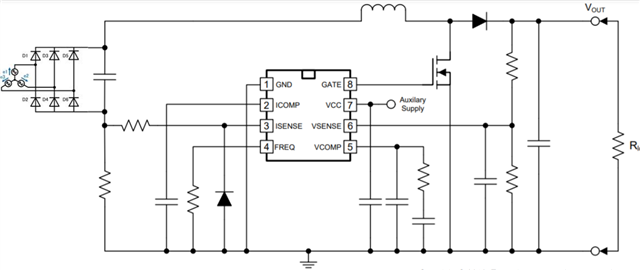
- At first glance I think that the single phase CCM would be good for my the UCC28019 would be a good and simple solution, or would you suggest something else?
- I checked the bridgeless PFC's, the totempole design (PMP20873) and the bi-directional bridgeless PFC, but if I need to add the two other phases from the generator this will be too complex and expensive I think.