This thread has been locked.

If you have a related question, please click the "Ask a related question" button in the top right corner. The newly created question will be automatically linked to this question.

TPS23882: No power issue

Part Number: TPS23882
Other Parts Discussed in Thread: , BOOST-PSEMTHR8-097, MSP-EXP430FR5969

Hi Sir,

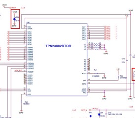
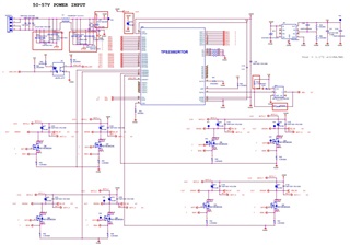
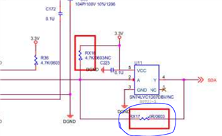
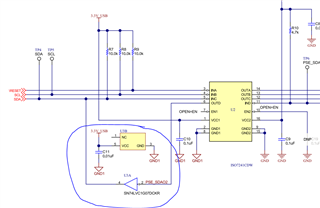
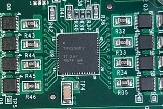
as attached is customer pin define and schematic.

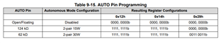
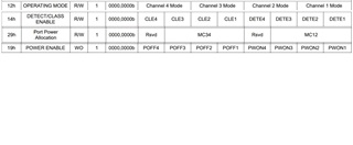
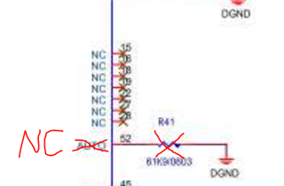
if customer need automatic or semi-auto mode, is pin_52 floating? or should it be connect to GND? and control it through i2c?

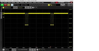
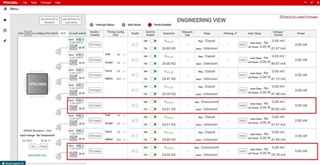
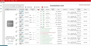
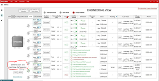
because current customer verify found that is no PoE function and no power.

also, can TPS23882B1 version control automatic and semi-auto throuth pin_52? no need for i2c control.

  • Hi Tommy,

    For clarification, TPS23882 does not support autonomous mode and therefore pin 52 on this device is NC. Leave this pin floating for this device and control operating mode through I2C.

    TPS23882B1 supports autonomous mode which eliminates the need for a host controller. Floating this pin will eliminate autonomous control, where tying this pin to ground through a resistor allows you to select port power allocation levels per the table below. Remember a 10nF cap is required in parallel with Rauto to ensure stability.

    I also want to highlight, auto mode and autonomous mode are two different modes. Autonmous mode eliminates the need for a host controller and can operate based on power allocation setting through selectable resistor on auto pin. Auto mode still requires a host to initialize the device though a series of I2C commands. TPS23882B1 can support both autonomous and auto mode, where TPS23882 only supports auto mode.

    Very Respectfully,

    Brandon Beader

  • Hi Brandon,

    thanks for your reply, and we have some question want to ask.

    1.After Power on, the address is all low, and the address does not run away.

    2.System reset is also sent to TPS23882 after power on

    3. The nINT pin is high at the moment of power-on, but it will remain low after, Will there be an interrupt signal in this state?

    4.pin_52 auto mode refer to EVM user guide 61.9k, and we try pin_52 floating, but it doesn't help.

    5.After the MOSFET terminal is connected to the PD, there is no voltage output from the gate, and the +/- on the RJ45 cable is measured directly, and the detect voltage of about 7V cannot be seen.

    6.Remove the I2C signal from the sample purchased by the customer before,and then do not set i2c, the power supply can still be normal at 30W. But this time the production does not work

    could learn from you and where modify need.

  • Hi Tommy,

    Can you upload PDF of full schematic for us to take a look at?

    Very Respectfully,

    Brandon Beader

  • Hi Brandon,

    as attached, 

    also, we wnat to know , if pin_52 is floating status now, should the following command be set? into the auto mode, right?

    TPS23882 schematic.pdf

  • Hi,

    TI is closed for the Thanksgiving holiday.

    We will get back to you next week!

    Thank you,

    Kevin

  • Hi Tommy,

    I want to clarify my point above. TPS23882 does NOT support autonomous mode and PIN on this device is a NC (no connect); TPS23882B1 is P2P and DOES support autonomous mode so PIN52 should be tied to ground with selectable resistor depending on port power allocation. I believe you are using TPS23882 and therefore PIN 52 should be NC.

    The schematic seems mostly okay, my only concern is RX17....what is purpose of this resistor? It seems this is directly shorting SN74LVC.

    Also is the SN74LVC being used as a buffer stage for SDAO? I would recommend using similar buffer stage as TPS23882EVM-008. See below:

    I also believe there is some initilization issues that is also cause for detection pulses. In order for auto mode to correct, you will need host commands to initilize device. Are you using GUI, TI FW, or your own FW to communicate through I2C?

    Very Respectfully,

    Brandon Beader

  • Hi Brandon,

    thanks, already working through i2c command.

    but there still some question we want to ask:

    1.after testing 100 units, happened that 10 units failed to supply power to certain port, seems that all of them are focus on port_4 and can not supply power.

      the measure waveform compare the abnormal port_4 and normal port_7.

    the figure below show the PoE output of RJ45 measure by port_4 when the PD is not connect:

    the figure below show the PoE output of RJ45 measure by port_7 when the PD is not connect:

    It seems that the idle stage is consistent.

    and the figure below show the waveform of PoE detection after port_4 is connect PD, and the power can not be supply.

    the figure below show the waveform of PoE detection after port_7 is connect to PD , normal power supply.

    may we know what is causing this problem? 

  • Hi Tommy,

    I am looking into this, I will get back to you with a response by COB 12 December.

    Very Respectfully,

    Brandon Beader

  • Hi Tommy,

    This is not behavior that we have seen before. It seems on port 4 it is cycling through detection and not initiating classification based on valid detection signature. Can you provide register dumps to see if port 4 is seeing valid detection condition? Also can you send me schematic to review to make sure there is no hardware issues with the board.

    For the 10 units we might need to take further evaluation. Either you can solder on these devices to our TPS23882EVM and see if issues still exist or send them to our team and we can test them and try and recreate the issue you are seeing with these devices.

    Very Respectfully,

    Brandon Beader

  • Hi Brandon,

    we foind some problem with port_4, if is address register problem, how do we fine-tune it?

    When problems occur,
    Register 05=0x88
    Register 09=0x08
    That is, CLSL4, DETC4, STRT4, 3 events have occurred

    Looks like a failure of PoE classification, right?

  • Hi Tommy,

    Can you provide full register dumps so I can pin point the issue here? It seems there is a timing issue here.

    Very Respectfully,

    Brandon Beader

  • Hi Tommy,

    What SRAM version are you using and have you patched in V07 which is current version?

    https://www.ti.com/lit/an/slvae12c/slvae12c.pdf

    Very Respectfully,

    Brandon Beader

  • Hi Brandon,

    for 10 fail units, verify as below and on TPS23882EVM-008. use the following EVM models.

    1. BOOST-PSEMTHR8-097 => switch board
    2. TPS23882EVM-008 => PoE board
    3. MSP-EXP430FR5969 => CPU board

    as the figure below, after the 8 ports all connect to the EVM board, setting standard mode, after the classification of each port is completed, but before the power supply starts. the current of port 1/ port 4 is obvious twice that of  other port.

    as figure below,

    next step, enable each port 1/port 2 to start power supply, it is found that port 1 show abnormal message , so it can not supply power.

    currently rule out is the problem of software setting.

    may we know what problem? thanks for your help.

    IC damaged?

  • Hi Brandon,

    i just know marking code, this can know the SRAM version?

  • Hi Tommy,

    It appears you are not loading SRAM, this will eliminate errors you are seeing. 

    We recommend using the latest version of SRAM code in order to ensure proper operation and IEEE compliance. Currently the lastest is SRAM v07 which can be patched in following these instructions.

    Very Respectfully,

    Brandon Beader

  • Hi Tommy,

    SRAM does not stay and therefore wheenver the device losses power, it will lose SRAM. SRAM will have to be loaded upon start up every time and I recommend you use SRAM v07.

    This SRAM can be requested on the TPS23882 device page and accessed in my secure resources.

    Very Respectfully,

    Brandon Beader

  • Hi Brandon,

    ok~thanks for your help and we will try it for latest version_v07.

    also,attached final PDF schematic.for your reference.

    tps23882_20221214 -PDF.pdf

  • Hi Tommy,

    I will review schematic and get back to you with my feedback. If you still see failures after loading SRAM, I would recommend doing ABA swap to confirm if this is IC issue or HW/setup issue.

    Very Respectfully,

    Brandon Beader