This thread has been locked.

If you have a related question, please click the "Ask a related question" button in the top right corner. The newly created question will be automatically linked to this question.

LM3464AEVAL: Cannot get output from Eval Board

Part Number: LM3464AEVAL
Other Parts Discussed in Thread: LM3464A, LM3464

Hello TI support., 

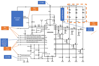
I'm in need of some help. At work I have a LM3464AEVAL board that I will eventually use to drive a string of LEDs and have control of with a PWM signal.

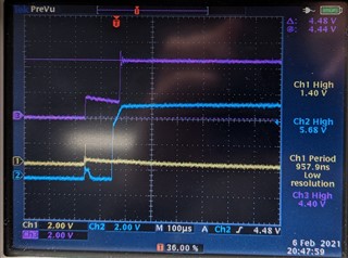
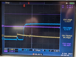
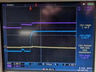
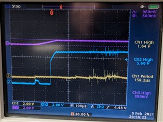
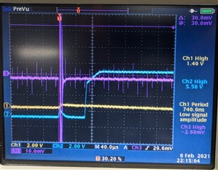
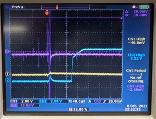
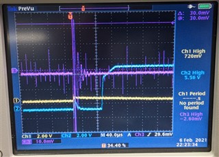
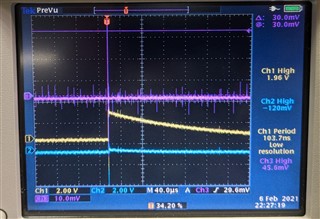
In order to test the eval board out before hooking it up to a expensive prototype LED rail, I'm using a power resistor. My rail voltage is only 27V as that is what the fwd voltage needs to be. The eval board supplys up to 350mA per channel, so I have a 250 ohm resistor in there. 

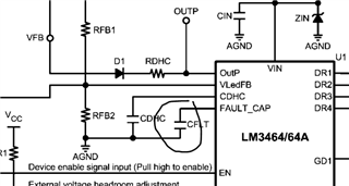
I have my DC supply hooked up to Vin and Pgnd. And the anode of the LED hooked up to Vin and the cathode hooked up to one of LED channels. Finally I have my PWM function generator hooked up to Dm and Pgnd. 

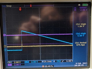
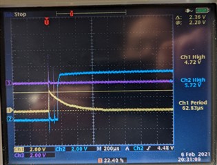
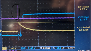
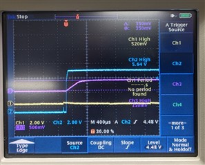
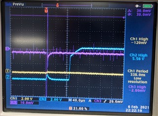
I have tried 3.3V PWM and 5V.  I also tried a 4ms period which I saw on one of the graphs as well as a much smaller period. 

Reading through the LM3464AEVAL and LM3464A datasheets, I can't seem to figure out what I'm missing. 

Note: I won't be using this with a AC/DC supply with feedback, so I won't be using the DHC function. 

Thanks in advance. 


  • hello Neil

    what is the current that you intend to set? I notice you mentioned that RSNS is set at 250ohm, this will lead to a quite small current.

    besides, it is mentioned that 27V is the forward voltage of LED string, so based on my understanding, to light LED, input voltage should be higher than 27V. you can try to increase it.

  • Right.. I don't know why I chose a 250 ohm resistor. Note: that's just a dummy load resistor.  The intention is to get the eval board working with the resistor load. Then move over to the LED rail. I

    I do need to reduce the current going to the LED rail when I work on that. The LED rail at 27V consumes 30 mA.  

    I could put a 100 ohm resistor there instead and increase the voltage to 30 ohms for a 30 mA current draw. 

    Regardless, I would expect to get something. out of it.  it wasn't outputting anything. 

  • hello Neil

    May I ask why LM3464 is chosen as this is actually not so commonly used? What is the potential application and its requirement here? I can check if we have a better choice. 

    At the same time, for the EVM board, can you help provide more information on how you configure by having some marks on the schematic below?

    what is the input voltage that you have applied? Do you mean you put a power resistor as an output instead of LEDs? what is the power resistor value, 250ohm? or 250ohm is the sense resistor RISNS which is in series with transistor?   

  • Mason, I didn't pick it out. I don't know why they chose this IC other than a eval board was available. I need to use the eval board for LED rail testing, so I need to figure out how to use it.

    In the future, I'm going to use a LP8864 instead.  On the side, I'm working on a circuit based on the LP8864. 

    For now, please see attached at how I'm using it and how I have it hooked up on my workbench in the lab. The power resistor is there in place of the LEDs, not as a RISNS replacement. 

    Thanks again.

  • hi Neil

    what is the frequency and duty cycle of the signal applied on DIM pin?

    Have you applied a voltage higher than 3V on enable pin? 

    please check if VCC voltage is around 6V, also check the waveform of Faultb pin

  • Mason, 

    I've adjusted the frequency from very low (10Hz) all the way to the 1Mhz range. And I have adjusted the duty cycle from 10% to 90%...  What is it supposed to be?

    Enable is not connected. But I measure 5.1V at it, so it is getting pulled high. 

    VCC is at 6.4V. 

    There is no waveform on Faultb. It is at ground potential. 

    I also swapped out my load resistor with a 100 ohm resistor and then a 50 ohm resistor.  I'm still not able to get it to turn on. 

    Thanks again. 

  • Hi neil

    then what is the value of RISENSE? Or you just keep it as default?

    I think certain fault has been triggered as the fault has been pulled down which is an fault indication. 
    I will check if operating with resistor load will cause the fault as the device is normally designed for LEDs

  • Mason,

    I Left RISNS1 as default. 200/1.13ohm=Iled=177mA. 

    My led rail works at 27V and 30mA, so I should put a 6.66 ohm resistor in there (200/6.66ohm=30mA)

    I will try this in the meantime. 

    Best regards

  • hello Neil

    For LM3464, there are several protections including LED open, LED short, OVP. The device continuously monitors voltage of DRx, SEx, GDx to see if any fault is triggered. So to further figure out, is it available at your side to get the waveforms of DRx, SEx, GDx together with Fault pin during start up? 

  • Mason, 

    took pictures of the scope triggered on power up. Specifically, I triggered on VFB (Blue Trace). After a little while, it goes to zero. Blue stays the same in all pictures. Yellow is the Fault B trace. Pink changes. Pink in this one is not hooked up. 

    For all of these, I hooked up one 27 volt, 30mA led rail to each of the 4 channels. I have a PWM signal going to the dim set to 10%, 5V peak, and 250 Hz .

    blue trace VFB, Yellow trace Faultb, Pink trace NA

    zoomed in time scale. Pink was on GD1

    Same zoom: Pink on the fet size of RD1 

    same zoom: pink on the fet's source or SE1. 

    Pink on the Vledfb test point

    Pink on Vdhc

    Other voltages:

    Vcc jumps to 6.24

    Thm+ jumps to 6.2

    Outp jumps to 5.8 but goes down to zero like Vfb

    EN goes to 5.04

    and sync stays at zero

    Thank you, 

    Neil

  • hello Neil

    based on the waveform, it seems the device triggers open protection. As the waveform is not quite clear, can you help double below:

    1. there is a GD pulse during start-up, can you zoom in and check if it reaches ~5V?

    2.  does the voltage of FAULT_CAP reach 3V?

    3. modify channel of RISNS to 10mV/div and check if this keeps below 30mV

  • 2. FAULT_CAP does not reach 3V. 

    3. RISNS1 through RISNS4 zoomed in. 

    I was curious to see what RISNS1 would look like when I keep the eval board plugged in and turn the PS on using it's switch instead of already having the ps on and hooking up the banana plug. It looks like I have the same sharp voltage pulse at RISNS1 that I had before. But the voltage on the PS takes a few ms to reach 27V. So I think this is just noise.: 

    1. GD1 with timescale zoomed in. I don't get anything over 200 mV on any of the GD's.  


    Thanks again, 

    Neil

  • I figured it out! 

    From page 6 from AN-2071: 

    Setting of VDHC_READY 
    When VRAIL reaches VDHC_READY, the voltage at the VLedFB pin of the LM3464A equals 2.5V. As the voltage at the VLedFB pin reaches 2.5V, the LM3464A performs a test for no long than 400uS to identify and exclude the idle (no LED connected) or failed (shorten / open circuit of LED string) output
    channels from the DHC loop.

    My VLedFB pin was only at 1.4V because my Vrail was 27V. I needed to increase Vrail to 48V to get VLefFB to = 2.5V. I just need to change Rfb1 or Rfb2 to scale it such that VledFB = 2.5V when Vrail is 27V. 

  • hello neil

    then how is the result after changing the resistor divider?

  • I will close this thread if no more questions.

  • Mason, 

    Thanks for your help. Yes, you can close it. To answer your previous question, the driver is working good now. 

    My real LED rail requires 44 volts so I changed Rfb1 to 45.3k so that the device turns on. 

    My rail also has a nominal max current of 120mA, so I set replaced RISNS with a 2.2k and 5.1 k. 

    Regards,

    Neil