This thread has been locked.

If you have a related question, please click the "Ask a related question" button in the top right corner. The newly created question will be automatically linked to this question.

TLV62084: Re-open Thread [TLV62084 Switching Frequency vs Load Current Characteristics]

Part Number: TLV62084

Hi Moheddin,

I'm updating about your request of previous my e2e thread.

Here is my thread : (+) TLV62084: TLV62084 Switching Frequency vs Load Current Characteristics - Power management forum - Power management - TI E2E support forums

Below is what you requested.

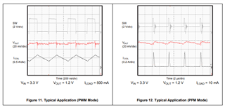
1. Vin measured at the IC pin

2. Inductor current waveform

3. switch node voltage including TON time.

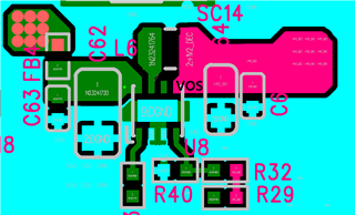
4. PCB layout to check the VOS pin connection.

Here is our data.

Default(VIN-5V,VOUT-1.2V) waveform.zip

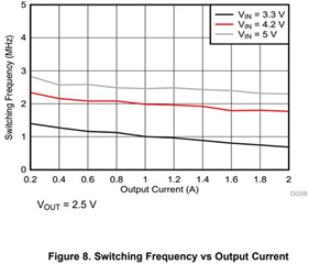
In addition, there is only VOUT=2.5V in the datasheet according to the current switching frequency chart, so a comparison test was conducted as follows.

Why is this difference happened? 

The test condition is (VIN=5V, R1=180k,R2=39.2k)

As in the above, it also shows a difference from the chart values below. (approximately 0.6MHz)

Frequency(MHz)

1.98

1.63

1.90

1.87

1.85

1.82

1.77

1.71

1.65

1.57

Current(A)

0.2

0.4

0.6

0.8

1.0

1.2

1.4

1.6

1.8

2.0

Graph on the data sheet .

Further inquiries

- What is the changing current section between PWM and PFM?

Could you please send your feedback about my each questions?

Best regards,

Michael

  • Hello Michael, 

    Thank you for the waveforms. I did not find any concern with the PCB layout.

    Why is this difference happened? 

    As I said before, In DCS control the switching frequency may vary due to many factors such as circuit losses, propagation delays and tolerance of the passive components. It depends upon the Inductor you used as well.

    I would recommend this document to under the frequency variation in DCS control (Understanding frequency variation in the DCS-Control(TM) topology)

    To verify with your issue, I conducted measurements again by using the TLV62084EVM (TLV62084AEVM-828 Evaluation Module) with the following conditions.

    Input Voltage = 5 V

    Output Voltage = 1.2 V

    Load Current = 0.2 A to 2 A (with 0.2 A step change)

    Please find the attached document. TLV62084.zip

    What is the changing current section between PWM and PFM?

    It depends upon your operating conditions such as, Vin, Vout and load current. You can simply verify with the waveform shape of the inductor or SW node and also by output voltage ripple.

    I have few questions.

    What is your desired switching frequency and operating conditions?

    If you want the device to operate at fixed switching frequency you can go with Forced PWM devices.

    If you need any help for selecting a right device as per your requirements for the application, please let me know I will support you.

    Thank you,

    Regards,

    Moheddin.

  • Hello Michael,

    If you don't have any further questions, please close the threat by clicking on Resolved.

    Thank you,

    Regards,

    Moheddin.