This thread has been locked.
If you have a related question, please click the "Ask a related question" button in the top right corner. The newly created question will be automatically linked to this question.
hi Team:
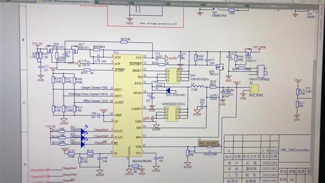
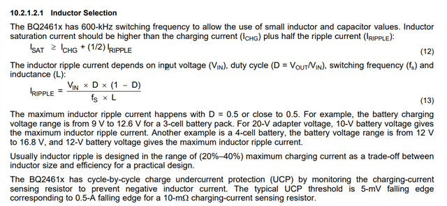
Recently, I encountered a problem when testing the BQ24610 battery charging EVM board with customer parameter. And the charging current does not reach the set value, Vsrp-Vsrn is less than 5mV, and the charging will stop automatically after 10 minutes of charging! Can you help to check what cause this issue ? tks!
setting parameter:
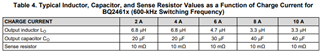
1.Charging current is set to 0.68A.
2.pre-charging current is 0.068A
3. input capacitor is 10μF
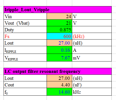
4. the output capacitor is 4.4μF
5. the inductance is 27μH
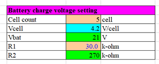
6.Input 24V, 5 lithium batteries, charging voltage 21V
result: The measured charging current is only 200mA, and the charging will stop after about 10 minutes.
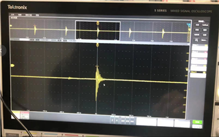
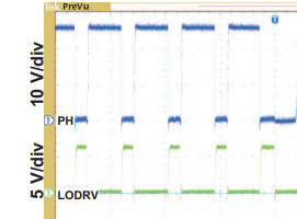
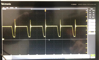
here attached the waveform of Vbtst:
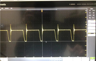
here attached the waveform of PH:
here attached the waveform of HIDRV:
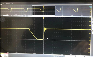
here attached the waveform of LODRV:
Hi Allen,
I have several questions regarding setup that will help me debug this problem.
What are the modifications done on the board? If there were modifications, have you followed the EVM user's guide test procedure to verify the modification is working?
What is the STAT1 STAT2 output when is occurred?
Did you apply a voltage to the TS pin (or connect the TS to to a thermistor)?
Did you enabled IINDPM by applying voltage to ACSET?
Is there a reason why you are using such large inductor? Below are some typical inductor, capacitor, and sense resistor value given in the datasheet.
Regards.
Hi Tommy:
tks for your comments.
here attached the SCH for further debug:
1.because of different setting of the charger current setting ,we just modify some parameters from the EVM.
2.STAT1 STAT2 output waveform will be sent be next day.
3.Apply a half of VREF voltage to the TS pin ,not connect to thermistor.
4.regarding to the setting of inductor. my customer follow below formula:
Charging current is set to 0.68A ,than the I ripple around 0.2A ,than we can calculate the L around 27uh. do you think it is okay with this method ?
Hi Allen,
Below are some comments on the schematic (following the checklist in this link):
Missing high frequency converter input capacitors (please refer to C10/C11 in the schematic checklist)
I cannot tell that is the top resistor value for the VFB resistor divider but I assume they are setup properly.
Were there a system load connected when you perform the test?
Regards.
Hi Tommy:
tks for your sharing of this checklist.
it seems like the checklist of C10/C11 is corresponding to the C72 (106,10uf), will the output capacitor less than 10μF cause abnormal charging?
according to the customer feedback, the STAT1 led will light up and STAT2 not light up when connect the BAT and adapter.
It proves that it is charging. After more than ten minutes, the two LED lights are off, indicating that the charging is complete or there is an error?
When the issue occurs, the system load is not connected.
I also have some questions want to ask :
1. Is the inductance L5 (27μH) selected in SCH too large? This inductance value is calculated by the formula in the data sheet.
2. This circuit diagram (the inductor parameter is different from the EVM) has been used by a product before, and it can be charged normally. So is it possible for LAYOUT to cause abnormal charging?
3.According to the LAYOUT suggestion in the spec, the IC and the inductor can be arranged in different layers. The sampling resistor and the MOS are required to be arranged on the same layer with the IC. In customer `s PCB, the IC and the sampling resistor are on the same layer, but different from the inductor and the MOS. Could this be the cause of abnormal charging?
Hi Allen,
C72 (10uF) looks more like C14 (high frequency noise decoupling cap in the checklist) to me.
When both STATs are off it indicates "charge suspend, timer fault, overvoltage, sleep mode, battery absent."
Also, the LODRV signal looks wrong to me, the waveform looks more like an oscillation than what it should be.
As for the output capacitor and inductor, it should work theoretically but we did not test the values your customer selected on the EVM before so we cannot guarantee it will work.
Layout can cause the large ringing shown in the waveform capture you provided. The ringing are at the absolute maximum rating of the device and exposure to absolute-maximum-rated conditions for extended periods may affect device reliability.
As for the layout, please refer to this layout guideline for more information.
Regards.
HI Tommy:
tks for your comments. Regarding to the charging current of 0.68A ,if the inductor L value comes from our formula and work theoretically , how can we convince customer to use this setting parameter? Any solid app note and test can be share?
tks again.