


We use TPSH000-Q1 (version A)
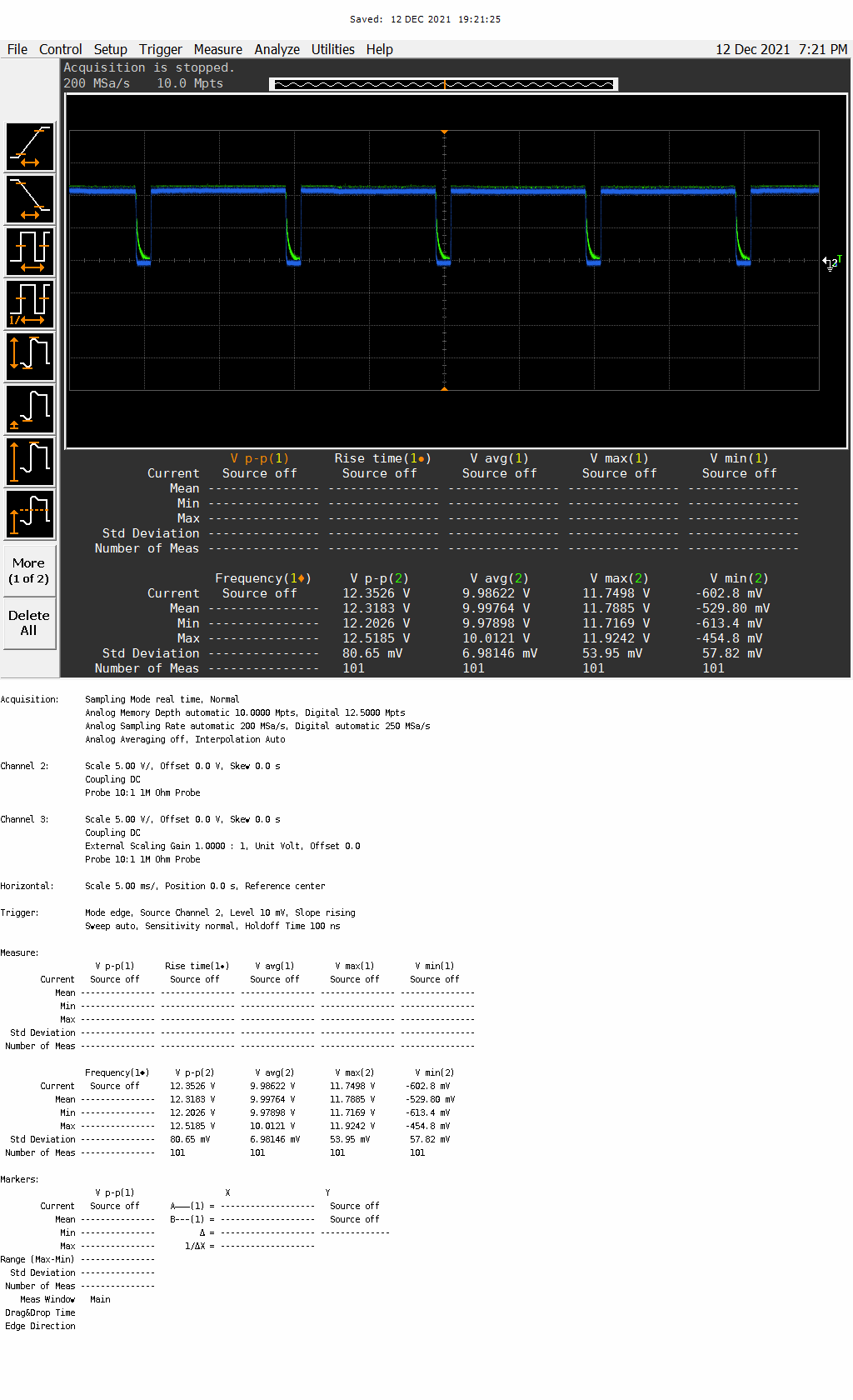
2-Channel Output Load are LED Module.
Chip support Open Load Detecting function.
But. We don't use open load function because it can't perform certain function.
So. Diag_EN : Disable
Diag_EN : Disable Status.
: Channel1 : OFF // Channle1 Output Load (connected),
Channel2 : OFF // Channel 1 Output Load (Connected)
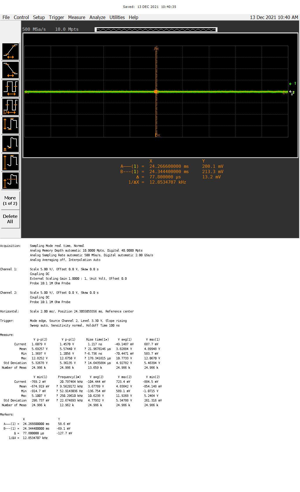
Diag EN : Disable
: Channel1 : ON // Channle1 Output Load (connected),
Channel2 : ON // Channel 1 Output Load (Connected)
Diag EN : Disable
: Channel1 : OFF// Channle1 Output Load (connected),
Channel2 : OFF // Channel 1 Output Lfoad (not Connected) <-- Open Load
Open Load Voltage is 5.2V (Vbat : 12V) // Output load voltage changes according to the value of Vbat
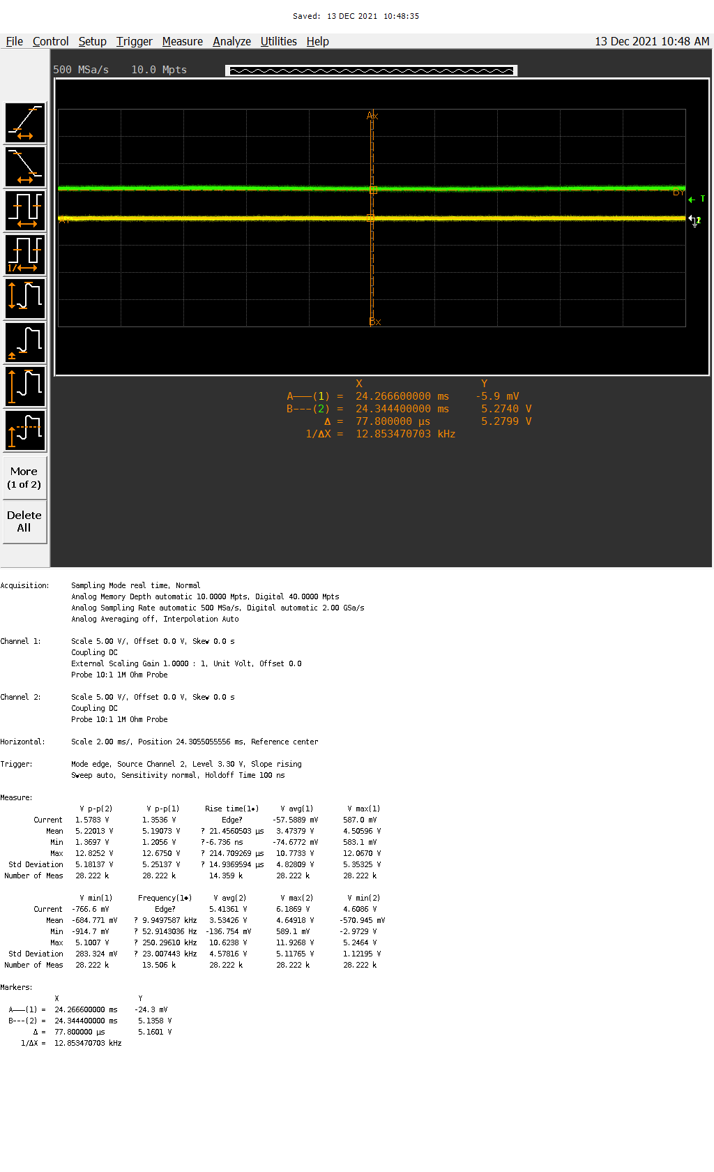
Diag EN : Enable
: Channel1 : OFF// Channle1 Output Load (connected),
Channel2 : OFF // Channel 1 Output Lfoad (not Connected) <-- Open Load
Diag En : Disable --> Enable
Output2 (Open Load) Voltage Change 5.2 V --> 2.2V

Problem
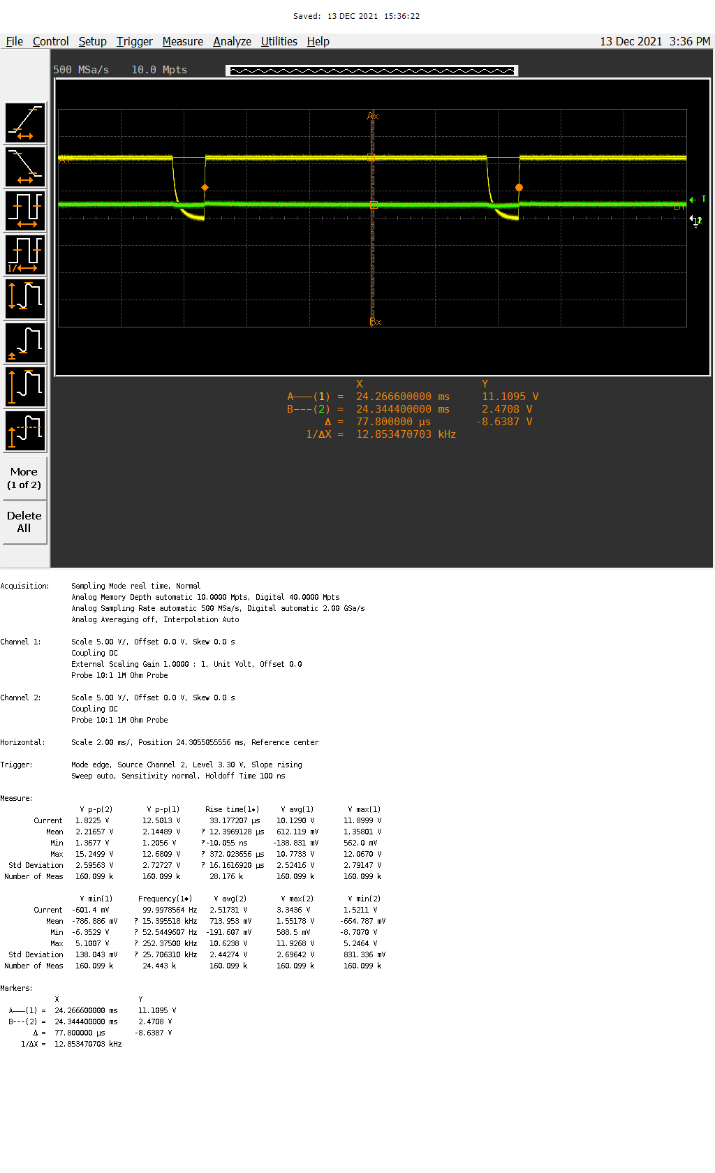
Diag EN : Disable
: Channel1 : ON // Channle1 Output Load (connected),
Channel2 : OFF // Channel 1 Output Lfoad (not Connected) <-- Open Load
if you turn on channel1 LED, the output2 channel voltage changes 5.2 V --> 2.4V ( Same as Diag EN : Enable When channel2 open load voltage)
We want to hold channel 2 voltage level (5.2V)
thank you
