This thread has been locked.

If you have a related question, please click the "Ask a related question" button in the top right corner. The newly created question will be automatically linked to this question.

TPS7H3301-SP: VENIL - Low-Level Input Voltage

Part Number: TPS7H3301-SP

Hello,

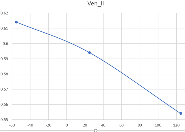
While performing WCA, I've noticed that VENILmax is quite low at 0.3V over full temperature.  I assume that VENILmax could be increased if not used over the full temperature range.  My application junction temperature is only 80C or 90C.  Could I please get a VENILmax per my application junction temperature?

Thank you.  

  • Kimberlee,

    The Venilmax of 0.3 V insures the terminator is disabled below that threshold.

    There is some margin on this specification.   However, testing insures the listed threshold.

    This parameter is influenced by the VDD voltage.   If operating at min Vdd, then the margin on this is reduced.

    Do you have a value for worst case VDD?   If so, I can use this along with the temperature to give you an estimate of max input threshold to disable device.

    Regards,

    Wade

  • Wade,

    My worst-case VDD voltage range is 3.18V - 3.43V.  

    Thanks.

  • After closer inspection of a recent characterization lot, the minimum off threshold looks like this on a sample of 30 units at 3V.

    A conservative approach would be to only derate by the change from 125C to 90C using the trend above.  This only achieves about 13mV due to temperature.

    Also can conservatively derate the offset due to VDD difference.  The shift in threshold at 2.375 to 3V is an increase of  ~80mV.

    So, a conservative increase would allow shifting of 13mV + 80mV = 93mV.   So, almost 400mV.   This solution would still essentially include our internal guardbands to datasheet limits.

    Typically this node would driven by a digital voltage level, and driving the node to ground is typically not an issue.

    I suspect you have pullups on this node that are pulled low with open drain outputs.

    Additionally,

    I would like to note that this device does not have internal soft start.   It can be challenging for the source of VLDOIN supply on startup when device is enabled after VLDOIN is already active.  Ie, the startup of the terminator is not relying on the soft start of the source VLDOIN supply.

    There is an active solution shown in the product folder to solve this.  It relies on using transistors to control the VTTSNS voltage when starting up to control inrush current.

    Additionally there is another new solution that has been verified, but has not been published as of this time.   It is very simple, and has other benefits.

    If your solution would benefit from this, I can provide more details.   It involves using VDDQSNS's UVLO threshold to enable/disable the device by using an appropriately sized isolation resistor from VDDQ supply.

    This will also improve your low level enable threshold concerns, as the UVLO threshold for VDDQSNS max is around 750mV (typical of 0.78).   The 0.75 is not currently specified, but will be added to test solution and datasheet in the future to bound this solution.

    If you can benefit from this solution, I can provide details via email.

    Regards,

    Wade

  • Wade,

    My datasheet specification from the driver which is an FPGA is VOLmax = 0.4V which is very close to closing with the 93mV increase.  I'm also working with that manufacturer for a more accurate VOLmax given the leakage current of the enable pin.  

    Please provide details regarding the solution you mentioned via email.

    I appreciate your help.  

  • Kimberlee,

    I will send you information via email regarding the alternate soft start methodology.

    Also, with respect to the Vol of your FPGA.  Likely this is specified with a specific IOL. 

    The EN pin for the terminator is high impedance with a leakage of +/- 1uA (25c).  Thus, it will not be loading the FPGA output.   The datasheet indicates only 25c, but this leakage is also less than +/- 1uA across temperature.  Actually in the low nA.

    If you there are other loads on the node that bring it closer to the IOL of the output, then I agree your analysis needs to accommodate the 400mV.

    If you do have only light loads that are less than the IOL, you will have much better margin to meet the 300mV Venil.

    The FPGA datasheet may have an Vol vs Iol typical graph that can help understand the additional margin.

    However, if your system will be enabling the terminator with VLDOIN already active, then I would recommend the alternate enable methodology that also provides soft start.  This is what I will be sending you shortly via email.

    Regards,

    Wade