This thread has been locked.

If you have a related question, please click the "Ask a related question" button in the top right corner. The newly created question will be automatically linked to this question.

LMR16010: radiated emission LMR16010

Part Number: LMR16010

Hello,

We have a problem with the radiated emission of our product.  It exceeds the limits of the CE radiated emission testing.  After a long search we didn’t find the source of the problem.  So to verify that the problem is in our product we tested also the LMR16010PEVM. To our surprise the sample problem appears on the reference design..

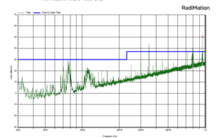
This the radiated emission of the LMR16010PEVM. 12V input 500mA output with a resistance static load.

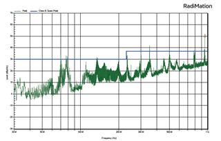
To verify that the leads are not emitting the problem we added filtering at the input and output leads.

It even got worse. The filtering in our product is even beter, the same peaks are visible only higher. at 20db above the line.

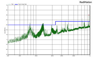
After a lengh search the conclusion is the LMR16010 itself is emitting the radiation.

Can someone at TI explain what the cause is of those emmitions.

Thanks!

  • Hi Ernst

    I need to confirm some items.

    Can you confirm that the EMI setup is not causing a baseline amount of emissions? Sometimes improper cable shielding can leak noise from the setup into the test results.

    Did you make sure that the leads on the static resistor load were as short as possible when testing? 

    What are you using as a filter for the input and output?

    Thanks,

    Andrew

  • Hi Andrew,

    This is the base line:

    The complete setup was inside the chamber. So no outside leakages. We used ferrite beads (280R at 100Mhz) on the input and output wiring.

    this is the development board without any load. at 12V input. Still the same patron..

    The same noise peaks we see in our product. That has a lot of filtering and use different components and layout.

    Thanks,

    Ernst

  • Hi Ernst,

    The delta between the baseline and the measured emissions with the device doesn't seem to be that big. Also, the first result you posted is a few DB off from passing.

    Could you try testing in a different chamber? The baseline emissions in that chamber doesn't even pass which gives me some pause.

    Also could you send a picture of your setup?

    Thanks,
    Andrew

  • Hi Andrew,

    The difference between the baseline is ca 25db at no load. That is the almost the complete range of clase B . You don't think that is a lot? What thinks TI is an acceptable value for this? In our end product the peaks are almost 50db at full load of the LMR16010.

    After a lot of testing my conclusion is that the LMR16010 itself is emitting those noises. Because the peaks produced by the ref design and our product are very simuliar in both have a peak at 75Mhz and 150 Mhz. That is curious Because both design have different switching speeds, PCB layout and components. So what is the source of those emissions?

    This is the chamber we did al of the testing:

    Sorry we don't have an array of CE test chambers available.

    Regards,

    Ernst

  • Hi Ernst,

    Can you send a better picture? I can't see the TI device, the load, the antenna, how the device is being powered, or the insulation on the chamber. Are you scanning for the horizontal and vertical orientation of the antenna? Are you using a 10m antenna or only 3m?

    Thanks,

    Andrew

  • Hello Ernst, 

    You may be able to improve the emissions with additional input filtering (e.g. LC filter on the input) and/or slowing down the switch rise time (e.g. R10 resistor on the evaluation board). 

    Here is an application note to help you design an input filter: 

    https://www.ti.com/lit/an/snva489c/snva489c.pdf

    This will help with both radiated and conducted EMI. 

    You can also experiment with the R10 resistor which is in series with the boot capacitor. This will have an impact on the converter efficiency, however. 

    Also, alternatively, you can try one of our power modules. Power modules are good options for lower EMI because they simplify the layout and help keep the critical for EMI loops as small as possible. See:

    https://www.ti.com/product/TPSM365R6 (65V 0.6A)

    https://www.ti.com/product/TPSM33625 (36V 2.5A)

    https://www.ti.com/product/TPSM5601R5H (60V 1.5A)

    https://www.ti.com/product/TPSM63602 (36V 2A)

    Regards, 
    Denislav