This thread has been locked.

If you have a related question, please click the "Ask a related question" button in the top right corner. The newly created question will be automatically linked to this question.

BQ24295: PMID Voltage does not drop to 0 when OTG pin is pulled LOW

Part Number: BQ24295
Other Parts Discussed in Thread: BQ24195, BQ25618

Hello,

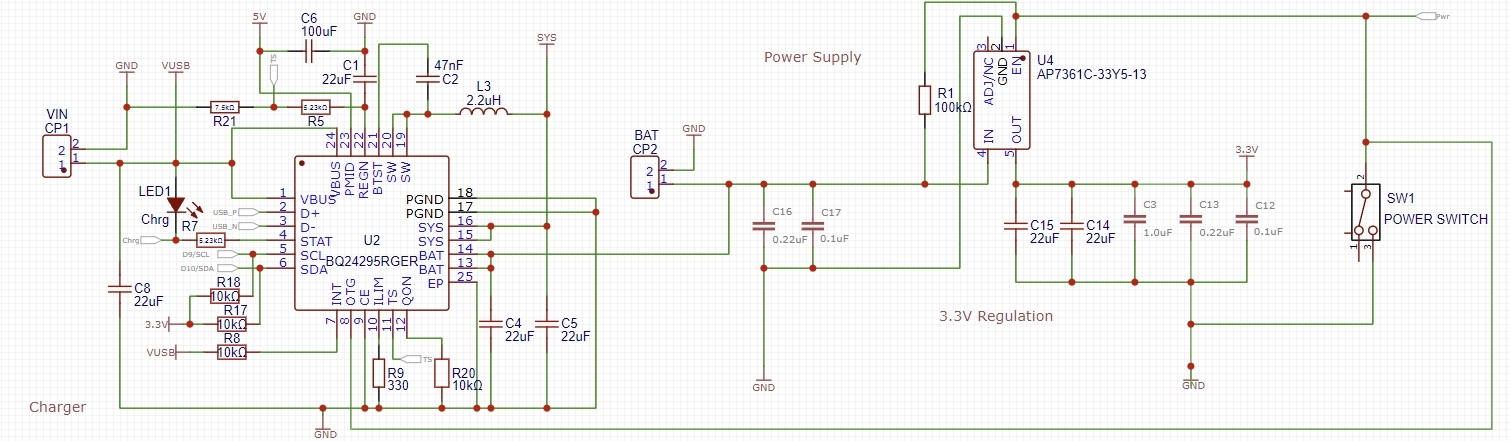
I'm using the BQ24295 ic on an embedded system where I need 5v boost for screen and leds (connected to PMID), and 3.3v for MCU (nRF52840). 3.3v is provided from an LDO connected to the Battery. I have a power switch to turn off the 3.3v LDO off when I don't use the board, so the MCU stops emitting radio packets and also in order to have no current drawn from the battery when not in use.

The power switch pulls down the EN signal of the LDO and is also connected to the OTG pin of the BQ24295, because I want the 5v coming on the PMID to be also cut off when I turn off the board.

However, when VBUS is disconnected and when OTG is pulled low the voltage on the PMID pin does not drop to 0v, it drops to SYS voltage, which is understandable as Q2 body diode connects PMID to SYS. And when I disable BATFET by I2C PMID goes to 0v.

Is there any simple hardware solution to avoid this and to have PMID completely disabled when OTG is pulled low ? If not is there another similar IC that could do this ?

  • HI Etienne,

    Unfortunately, all of our chargers with OTG at the PMID output have that body diode to connect the battery less a diode drop to PMID.  If you can change to a charger with OTG output at VBUS (one without the last number being 5), then there would no voltage on VBUS when OTG is disabled.  Or you can add an external PFET like shown below for BQ24195 but on the PMID pin instead of VBUS:

    The gate of Q2 would be driven by the OTG pin.

    Or, if your application is okay with 1.5A charge current and 1A OTG current, you can could use BQ25618/9 as below:

    Regards,

    Jeff

  • Hi Jeff,

    Thanks for the reply.

    Unfortunately BQ25618/9 is not supported by the pcb/smt provider I use (JLCPCB). So the only option left would be adding the external FETs.

    However I'm struggling to find available space on my board to place these Fets (Q1 and Q2). I've found a quite small Q2 (TPM2008P3), but for Q1 I only found PFets with SOT23 packages.

    Do I need to add the 1nf capacitor on Q1 (is it for stability ?).

    Also since I already have a 100 K pullup on the OTG and EN pin that is pulled low by my power switch, I believe I don't need R8 and R9 right ?

  • Hi Etienne,

    Q2 NFET doesn't need to be low RDSon so can be low cost and small.  Q1 needs to below RDSon to prevent voltage drop that will impact your application at full current.

    R8 and R9 and the Vth for the NFET form a crude comparator that prevents the NFET from turning on (and therefore PFET) until the divided down input voltage is above the NFET Vth.  The 1nF shorts out the 10kohm when the NFET turns on and then slowly charges, which should turn on the PFET slowly.  At PFET turn off the 10kohm and 1nF slow down turn off.  I recommend the soft starting 10kohm and 1nF.

    Regards,

    Jeff