This thread has been locked.

If you have a related question, please click the "Ask a related question" button in the top right corner. The newly created question will be automatically linked to this question.

TPS7A52: Bias voltage

Part Number: TPS7A52
Other Parts Discussed in Thread: TIDA-01232, TPS7A57, TPS7A94, OPA333

I am designing a 5V – 1.8A power rail with the TPS7A52. The output noise needs to be as low as possible and the transient response as fast as possible.

The input voltage is of the rail is 6.10V, so to keep the power dissipation of the IC around 1W I am going to use a rectifier that has a drop of 500mV @ 2A.

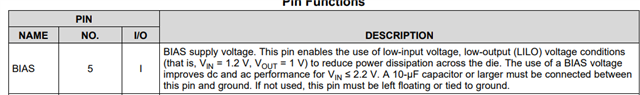
The IC is equipped with a bias voltage input. For the bias voltage input I can use the 6.1V input voltage.

Two questions: Does it make sense to use the 6.1V at the bias input and second what type of capacitor is the best option for the bias supply, a tantalum or ceramic cap or a combination of both?

I am looking forward to you advise.

  • Hi Wiebren,

    The Bias pin on TPS7A52 is only recommended for low-input low-output (LILO) applications in which VIN < 1.4V. It can help the performance of the LDO when VIN <= 2.2V, however in your application VIN = 5.6V.

    In your application it would make sense to keep the Bias pin floating or tied to GND.

    Regards,

    Andres

  • Hello Andres,

    Thank you for your reply.

    I want to look at an alternative design by using two TPS7A52 in parallel. According to the specsheet this can be done by following the instructions in the "TI Designs: TIDA-01232

    My concern is that this is no option for the TPS7A52 even when you use 0.1% tolerante resistors in the "feedback resistor network" to set the output voltage of the two regulators. 

    What are your thought?

    Regards, Wiebren

  • Hi Wiebren,

    We will soon be releasing to the web a new design for parallel LDOs which goes more in depth on this topic. Meanwhile, if there is a concern that TPS7A52 won't be an option, I can think of two alternatives with lower noise.

    One would be TPS7A57 which has 2.1uVRMS of noise and superior load transient response.

    Another option would be TPS7A94 which has 0.46uVRMS of noise.

      TPS7A57 TPS7A94
    Iout(Max)(A) 5 1
    Vin(Max)(V) 6 5.7
    Vin(Min)(V) 0.7 1.7
    Vout(Max)(V) 5.2 5.5
    Vout(Min)(V) 0.5 ---
    PSRR @ 100
    KHz(dB)
    60 78
    Noise(uVrms) 2.1 0.46
    Accuracy(%) 1 1
    Dropout voltage
    (Vdo)(Typ)(mV)
    75 150
    Iq(Typ)
    (mA)
    5 15
    Thermal resistance
    θJA(°C/W)
    40.3 46
    Operating temperature
    range(C)
    -40 to 125 -40 to 125
    Package size: mm2 9 mm2: 3 x 3 (WQFN|16) 9 mm2: 3 x 3 (WSON|10)
    Packages WQFN|16 WSON|10

    Regards,

    Andres

  • Hello Andres,

    Thank you for your reply.

    My concern for the design in general is heat. When I use one TPS7A52 and a rectifier with a Vf of 500mV both units will dissipate 1W @ 2A. By running two units in parallel all components will dissipate 500mW, which is in my opinion a better option. Maybe you have a different point of view and the 1W should not be a problem. The PCB is 2Oz double sided 40x120mm.

    My concern about the "TI Designs: TIDA-01232" is that the 0.1% resistors will give a worst case output voltage difference between the two LDO's of 15mV. This will not be compensated by the ballast resistors in my opinion. Maybe I am wrong, please advise.

    I am now looking at the alternative option "6A Current-Sharing Dual LDO" which is using a OPA333. My first problem is that the max input voltage of the OPA 333 is 5.5V max. It is not clear for me that I can use the 5V output of one TPS7A52 to power the op-amp.

    Regards, Wiebren  

  • Hi Wiebren,

    If heat is a main concern, TPS7A57 has a lower thermal resistance than TPS7A52. At 1W of dissipation you can expect an increase in temperature by 40ºC. So, as long as the ambient temperature is lower than 85ºC there should be no problems with the device. Meanwhile TPS7A52 will handle only up to an ambient temperature of 56ºC at Pd = 1W. If you want to know how to enhance your PCB for better thermals I recommend reading this article: https://www.ti.com/lit/an/slvae85/slvae85.pdf?ts=1673981920872

    Let me get a second opinion on the compensation of the ballast resistors regarding TIDA-01232.

    Regarding your question about "6A Current-Sharing Dual LDO" is your question about using a TPS7A52 to power the op-amp here?

    If so, you may run into problems since you require 5.5V for this design and TPS7A52 has a max output voltage of 5.2V.

    I would once again advise on trying TPS7A57 since it seems it would be a smaller solution size than using 2 to 3 TPS7A52's.

    Regards,

    Andres

  • Hello Andreas,

    Thank you for your update. I have checked your recommended TPS7A57 and this is a unit with even better specs. My concern is that 2 x TPS7A52 will run cooler when both LDOs are dissipating 1W, than a single TPS7A57 that needs to dissipate 2W.

    I have started a new post in the opamp section for assistance with a higher voltage alternative for the OPA333. The Opamps have been found and now we are discussing and improving the circuit further.

    Thnx, Wiebren

  • Hello Andres,

    Thank you for the information and links, much appreciated. 

    Regards, Wiebren