Other Parts Discussed in Thread: TPS7A7001, TPS7A57
Hi,
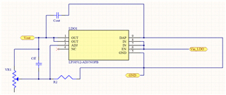
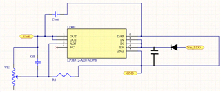
We configured this LDO as shown in the Typical Application circuit diagram.
Vin = 5V
Vout = 3.3V typical
Maximum load current 500mA
R1 (feedback) = Trimmer Resistor (3296W-1-103LF)
R2 = 1kohm thick film resistor (RS73F1JTTD1001B)
Cin = Cout = 10uF ceramic capacitor (TMF325B7106KMHP)
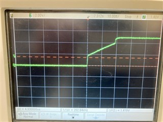
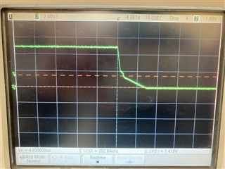
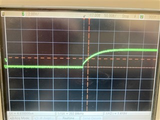
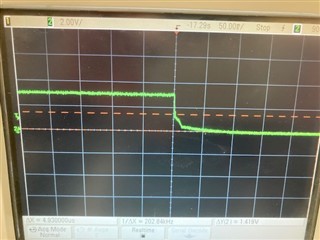
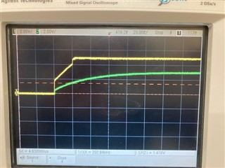
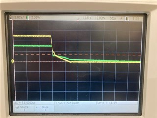
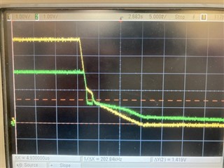
3 out of 5 boards tested at room temperature have the following behavior after a few days of usage. Vout = Vin = 5V. When we probed Vadj its value now changes with trimmer resistor, e.g. Vadj = 0.6V if R1 is set to 2.315kohm. Vadj should be fixed at 0.5V.
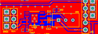
2-layer PCB