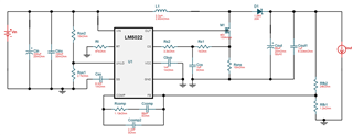
This thread has been locked.

If you have a related question, please click the "Ask a related question" button in the top right corner. The newly created question will be automatically linked to this question.

LM5022: BOOST CONVERTER DESIGN - CHANGING / GETTING DESIRED OUTPUT - REG

Part Number: LM5022

Hi,

REQUIREMENT:

Vin = 15 V;

Vout = 24 V;

Iout = 6 A;

HERE I'M ATTACHING MY CIRCUIT. 

MY PROBLEM:

I'M GETTING 28 V AS MY OUTPUT. I WANT TO CONTROL MY OUTPUT TO 24 V.

PLEASE GUIDE ME WHAT TO CHAGE IN MY DESIGN SO AS TO GET A DESIRED OUTPUT OF 24 V.

Thanks in advance

  • Hi Subash,

    Thank you for using E2E forums, regarding your query the FB voltage divider is not set to the right values in order for you to get 24V output. According to my calculation with the current set up you will get around 27V to 26V output. Maybe check your FB voltage divider circuit? The FB voltage reference is 1.25V on average so I would recalculate the FB divider circuit.

    Thank you

    Regards,

    Haroon

  • @haroon, Thanks for the reply. What should be the voltage at the FB pin.? what changes the output? is it RT resistor? or Comp resistor and capacitors? 

  • Hi Subash,

    The Vout is changed by changing the FB divider circuit, the upper resistor and the lower resistor that makes the voltage divider and based on the resistance values and the fact that the FB pin will have 1.25V on average you can calculate the Vout.

    BR,

    Haroon

  • Hello Subash,

    I have not seen an update from you for the last 24 days, so I assume the questions are answered and the issue is solved.
    I close this thread now. If there is still something open, please reply and the thread will get opened again.
    If you have any other question or of the thread has been locked, please open a new one.

    Clicking the Resolved Button also helps us to maintain this forum.

    Best regards,
    Harry

  • issued is solved