Other Parts Discussed in Thread: PMP9656, PMP3162, PMP8380, UCC27511
Hi TI Partner,
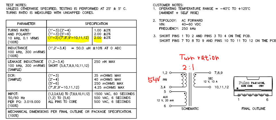
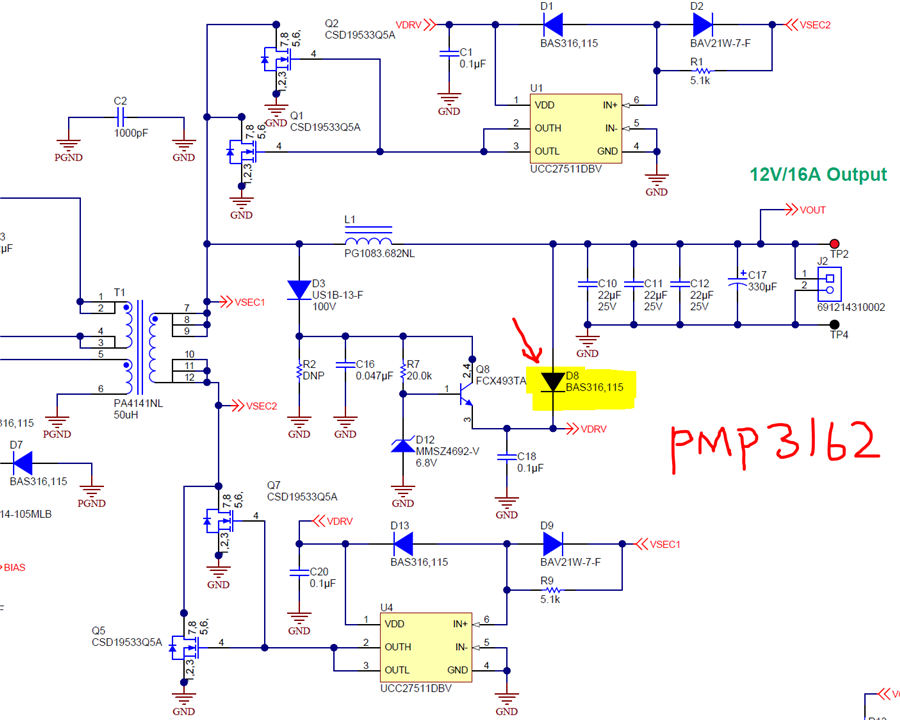
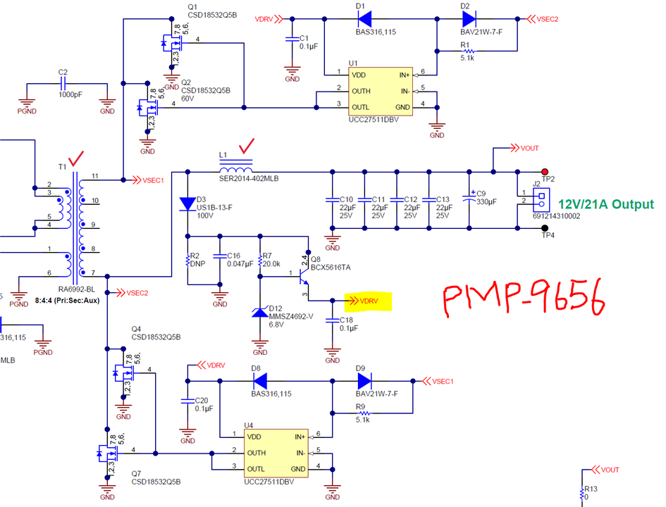
After review 3 reference design for 54V to 12V application, I have some questions need confirm with you.
Q1: What is the function of "D8", I see it on PMP3162 sch, but removed on PMP9656?
Q2: in PMP9656 sch, "VDRV" Voltage is?
Q2-1: The "VDRV" voltage is determine the SR-FET Gare-drive voltage level, right?
Q2-2: If I want to adjust the SR-FET Gate-drive Voltage level, how can I do?
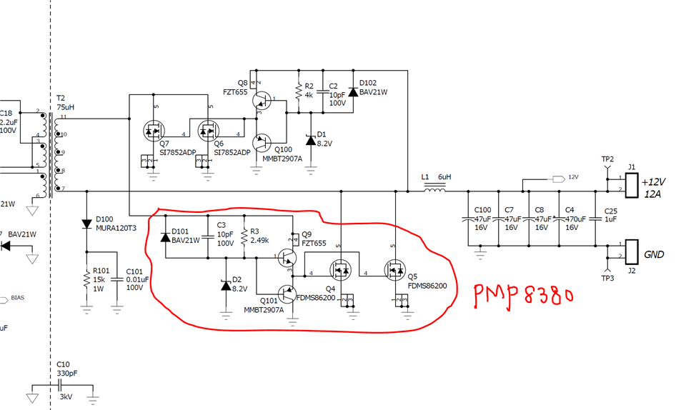
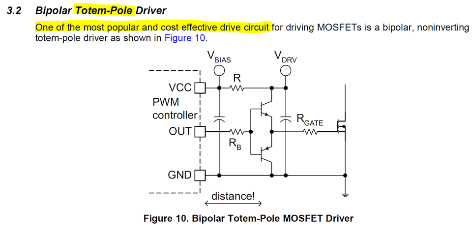
In PMP8380 circuit, the SR-FET Gate drive circuit that is using Totem-Pole topology.
Q3: For cost effective consideration, may I use Totem-Pole circuit to replace UCC27511 drive circuit?
Q3-1: If yes, which component parameter need to noted for higher output power design (12V/12A=>12V/21A)?
Q3-2: if not, could you recommend a suitable Gate-drive circuit to me for reference.
Thanks a lot!