This thread has been locked.

If you have a related question, please click the "Ask a related question" button in the top right corner. The newly created question will be automatically linked to this question.

TPS48111Q1EVM: test steps

Part Number: TPS48111Q1EVM

Hi Team,

Please confirm whether there is a problem with the test steps:
1. Ground inp and inp_G;
2. Connect to 53.5V DC power supply;
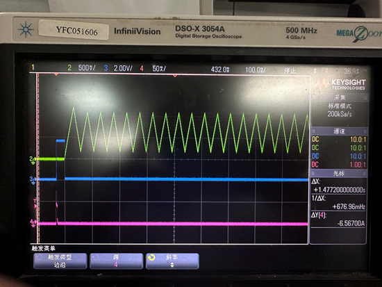
3. Inp pull high to enable, test PU and VOUT

Regards,

Charlie

  • Hi Charlie,

    We have to first pre-charge the output capacitors else remove C2, C3 and C15 to test with INP 

    Please refer EVM user's guide https://www.ti.com/lit/ug/sluuck8a/sluuck8a.pdf 

    Best Regards,

    Rakesh

  • Hi Rakesh,

    Thanks for your support.

    I have carefully read the datasheet and EVM User guide. But I still encounter the following problems, I hope you can continue to support:

    1. When the customer first started testing the EVM, nothing was connected to the output terminal, and the output was normal.

    Then ground the inp_g, and then there is no output, and the overcurrent light will be on, and then disconnect the ground point of inp_g, and there is be no output. I suspect that the EVM got corrupted during testing, but don't know why.

    2. In the new EVM, replace the output capacitors so that the total output capacitor value is 10uF. When the input voltage is 30V, Auto-Retry Response for an Overcurrent Fault is normal. But when the input voltage is 48V, Auto-Retry Response for an Overcurrent Fault is abnormal. The abnormal performance is that the TMR has been charging and discharging, and the IC does not restart. 

    The picture below has less than 32 cycles, but in the actual test, it is found that it still does not start when it reaches 32 cycles. The waveform is captured by the oscilloscope trigger current signal.

    What is the possible reason? Is it useful to increase the value of R9?

    Regards,

    Charlie

  • Hi Charlie,

    I will go through it and get back by end of day today

    Best Regards,

    Rakesh

  • Hi Rakesh,

    Thanks for your support.

    I suggest customers to grab the waveforms of TMR and FLT_I, enlarge the time scale to see FLT_I, there is still no restart pulse;

    When the test was repeated for the third time, the board was powered on and did not start. When checking the voltage, it was found that BST and SRC were short-circuited (after the external capacitor was removed, it was still short-circuited). What could be the reason? 

    Is the chip damaged due to excessive di surge current? Thanks.

    Regards,

    Charlie

  • Hi Charlie,

    If we have output capacitance, then we need to do either of the following for successful start up.

    1. Make INP = LOW and precharge the Cout through pre-charge FET

    2. if precharge FET is not used, increase R10 to 100k, populate R15 and C9

    without that, there could be stress on the bootstrap section.

    If R23 is installed on TMR pin, the device will latch off for overcurrent fault

    Best Regards,

    Rakesh

  • Hi Rakesh,

    Thanks for your support.

    Is your suggestion to increase the drive resistor and slow down the speed at which the switch turns on and off?

     It was found that BST and SRC were short-circuited. Is the current exceeding 3.7A and 4A causing breakdown? 

    If there is no precharge, how to ensure that the MOSFET can start up quickly under capacitive load? Thanks.

    Regards,

    Charlie

  • Hi Charlie,

    The current through the BST and SRC pins is limited by the internal pull-up and pull-down FET. So, i feel the voltage between BST-SRC might have exceeded 16V during your tests as reason for short between BST and SRC

    Please use design calculator under product folder to size the dvdt components

  • Hi Rakesh,

    Thank you for your analysis. 

    The capacitor between BST-SRC will stop charging to 12V. Then the MOSFET is turned on, Ciss is charged, and the voltage of VGS should not exceed 12V. Why do you doubt that the voltage between BST-SRC might have exceeded 16V?

    The customer is using the EVM board for testing. Are the parameters of the EVM board verified? Right? Thanks.

    Regards,

    Charlie

  • Hi Charlie,

    EVM board are verified. Can you tell us step by step how customer is testing the EVM.

    We have requested for test waveforms. Can you help with those

    Best regards 

    Rakesh