This thread has been locked.

If you have a related question, please click the "Ask a related question" button in the top right corner. The newly created question will be automatically linked to this question.

LM5023-2NBEVM: Design Problem With Higher Frequency Transformer

Part Number: LM5023-2NBEVM
Other Parts Discussed in Thread: LM5023

Hello,

I had bought a LM5023 Evaluation Board (LM5023-2NBEVM) and tried to simulate it as it is in Tina software. It is perfectly working for transformers designed for 55kHz frequency and quasi resonant waveform was also observed. 

In the data sheet of LM5023, it is mentioned that the IC is capable to handle the frequency up-to 130kHz. Hence I tried with the transformer which is designed for 100kHz frequency, but while simulation instead of quasi resonant, valley switching is obtained and after that convergence error occurs.

I had modified the values in the voltage divider of QR pin  by considering the calculations given in data sheet of LM5023 (eq. 45 (R1), eq. 51 (R2), eq. 54 (Cd)).
What other parameters I need to modify to get the quasi resonant waveform at 100kHz?

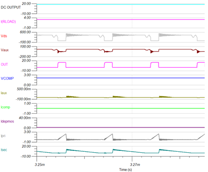
I am attaching my simulation waveform just before convergence occurs for 100kHz frequency transformer.


Regards,
Raj

  • Hello Raj, 

    Thank you for your interest in the LM5023 QR flyback controller.

    This controller has a maximum frequency clamp at 130kHz and will not allow switching at higher frequencies.  Figure 13 on page 17 of the LM5023 datasheet indicates the general variation of switching frequency versus normalized output power.  The target switching frequency (fSW) is generally chosen at full power and lowest input line voltage.  fSW then increases with higher input voltage, for any given output power level still operating in QR mode.  Choosing fSW = 100kHz at low line, full power leaves little room for QR operation at lower power levels or higher Vin, before being clamped into DCM valley-switching.  

    Scaling the vertical axis to 25kHz per division, 100kHz corresponds to the 4th horizontal line from the bottom.  It is possible that high-line operation would work only in DCM at all power levels (until skip mode).  This tends to diminish the effectiveness of QR for higher efficiency at medium power levels. 

    For your simulation, I suggest that you start a new design with the fSW target of 100kHz, starting at equation 13 on page 15, rather than take the EVM design and simply change the transformer and R1, R2, Cd.  Other components, such as Rsense, may also need to change.

    I'm not sure what is causing the convergence issues, but the heavy ringing evident on Iaux and Vaux may be contributing to that.  
    I suggest to critically dampen these oscillations with an RC snubber across the component that is the most likely source of this ringing.   
    Other than that, try adjusting some of the simulation parameters such as minimum time step, minimum error, etc. to help with convergence.

    Regards,
    Ulrich

  • Thanks Ulrich for the explanation.