Hello,
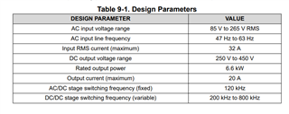
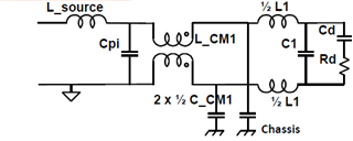
I am trying to design active EMI filter using TPSF12C1-Q1. Regarding that, firstly I have designed a passive filter by following procedure from Biricha digital. That passive filter circuit is shown below-
Now, I want to replace common mode capacitors by TPSF12C1-Q1 and hence reduce CM choke size as explained in TI datasheet of the mentioned part number. But I am having some doubts in active filter circuit diagram by Texas instruments which is shown below-
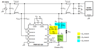
Can you help regarding the following points-
- How to select/calculate sense capacitors, Injection capacitor which are replacing Y-capacitors(CM) value ? (In datasheet, values are for the given typical application example)
- How to calculate reduced value of CM chokes compared to passive filter case?
- Why there are two CM chokes in active filter circuit?
I have gone through the datasheet and QuickStart calculator excel sheet for TPSF12C1-Q1, but not completely sure how to use it for my design as sheet is protected.
Quick response would be appreciated.
Thanks,
Jasvant Singh