This thread has been locked.

If you have a related question, please click the "Ask a related question" button in the top right corner. The newly created question will be automatically linked to this question.

BQ24074: BQ24074 CHG status does not change

Part Number: BQ24074

1) The battery charges "successfully" as in, as measured by a DMM, the current into the battery is dropping below the termination current and the voltage is up ~4.2V. I started with a battery at 3.6V.

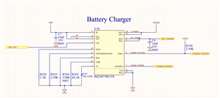
2) The CHG pin does not change. It is always low.

3) I would also expect the CHG pin to go HI-Z when I remove the battery entirely, and it just stays low.

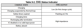
4) If I disable the IC, CHG does go hi-z as expected with table 9-2, so the output isn't physically broken

CHARGE-STATUS# port used to be connected to a pin on my MCU, but I've since cut the trace entirely and I'm measuring at the pullup resistor.

  • Hi Chris,

    Welcome to E2E!

    Are you able to share what the voltage at the ISET? I'm glad you're able to measure the current out of the battery but it'd be good to also use the voltage to see if the device is still trying to provide current. 

    Thanks for the schematic as well. I do notice that you don't have any capacitors on the OUT pin. We do require that the OUT pin have a bypass capacitor in the range of 4.7uF to 47uF. 

    Do you have multiple boards with this behavior? 

    Best Regards,

    Anthony Pham

  • Thanks!

    FYI,  when I remove the battery completely, the voltage on the BAT pins is ~4.2V....so it does appear that the chip is attempting to charge the battery.

    With the battery completely removed, the voltage on iset is 0.2V

    I do have a pair of 10uF capacitors on =Vout on a different page. +Vout is going into a +3v3 LDO, which is where the +3v3 you see on this page is coming from. That schematic page has the two 10uF caps there.

    We have about a dozen boards with this behavior (100%).

  • Hi Chris,

    Can you try with the battery not removed and measure the ISET pin? I'd like to see the voltage when you are saying that the device should have the /CHG pin in HI-Z.

    The battery charges "successfully" as in, as measured by a DMM, the current into the battery is dropping below the termination current and the voltage is up ~4.2V. I started with a battery at 3.6V.

    When you say the "current in into the battery is dropping below termination" , does this mean you still see some current that isn't approximately 0 mA?

    I do have a pair of 10uF capacitors on =Vout on a different page. +Vout is going into a +3v3 LDO, which is where the +3v3 you see on this page is coming from. That schematic page has the two 10uF caps there.

    Awesome! Just thought I'd double check. 

    Best Regards,

    Anthony Pham

  • 1) I believe I've set termination current to ~30mA based on the resistors chosen

    2) My +Vin current with the battery unplugged is ~130mA and, when I plug in a "full-ish" battery, it's about ~170 mA (and it drops towards 140mA after a time)....that was the basis of my guess that the charge current was going below the termination current.....also if I leave the battery plugged in overnight, the CHG status still doesn't change...and at that point it's back to ~130mA 'baseline' current....which I also assume is a sign that the battery is full

    And FYI the V on ISET is around 0.3V and dropping slowly

    3) I'm using a 800mAh battery so overnight it should be charged up

    4) Should I expect CHG to be hi-z when there's no battery plugged in? Am I misinterpreting the datasheet?

  • Hi Chris,

    Right, you do have a 30 mA termination set. 

    I leave the battery plugged in overnight, the CHG status still doesn't change...and at that point it's back to ~130mA 'baseline' current....which I also assume is a sign that the battery is full

    This would be correct, I would expect the same thing looking at your charge current (~300 mA) and battery capacity (800 mAh). 

    And FYI the V on ISET is around 0.3V and dropping slowly

    Is this when you see the input current at about 130 mA? 0.3 V would translate to about 36 mA which would mean the device doesn't want to terminate yet. 

    Can you measure the voltage when your input current is 130 mA. 

    Should I expect CHG to be hi-z when there's no battery plugged in? Am I misinterpreting the datasheet?

    I believe this is correct. 

    By chance, can you tell me what the current capacity of your input is? And also wanted to check, is the 130 mA coming from your load at the OUT pin?

    Best Regards,

    Anthony Pham

  • My input in this instance is a 5V usb output for ease of testing. The 130 mA is measured at the input to this circuit. It's the current coming out of the USB port, with nothing else attached (measured with a normal USB power meter)

    Is this when you see the input current at about 130 mA? 0.3 V would translate to about 36 mA which would mean the device doesn't want to terminate yet. 

    With a fully charged battery, I see about 130mA whether the battery is plugged in or not. Not the best meter in the world, so it could be an extra ~0mA at most.  However, I took an oscope probe of the ISET pin this AM and saw that the signal is actually a pulse train.

    With battery unplugged:

    • 5Vp-p*
    • 9.7kHz
    • 3% duty cycle
    • CHG status: LOW

    With full battery plugged in

    • 3.5Vp-p*
    • 4.9kHz
    • ~10% duty
    • CHG Status: LOW

    With non-full battery plugged in:

    • ~3.5Vp-p (shape much different)*
    • ~9.7kHz
    • ~80% duty
    • CHG Status: LOW

    FYI when a full battery is plugged in, the ISET waveform is bouncing around a bit, like it's going back and forth between two states and the frequency is going back and forth from ~5kHz to ~10kHz

    Edit: My scope impedance settings were off, I updated the voltages above.

  • Hey Chris,

    I don't expect a signal with that level of noise. I actually expect a DC voltage on the ISET pin. Are you able to share an image by change of the waveforms you gathered?

    Are you seeing this on one board? Do you have multiple boards that show this behavior?

    Are you able to probe the pin using a tip-and-barrel method with your oscilloscope?

    Best regards,

    Anthony Pham

  • After you mentioned the waveforms being abnormal, I ended up investigating the output ~4.4V from the BQ. It had a bit more ripple than I anticipated as well. After probing around a bit, I believe the issue I had was due to an interaction with a downstream switching regulator: When I changed the other regulator's switching frequency, the BQ24074 behaved as expected.....So perhaps the BQ24074 was looping through it's charge flow diagrams and being fooled into error conditions by the downstream converter.

    Still investigating but I believe that the 20uF output capacitance in this instance was insufficient and will be bumping to 47uF to test further.

  • Hey Chris,

    Glad to hear that we have a source for the noise, looking forward to your update.

    Best Regards,

    Anthony Pham