This thread has been locked.

If you have a related question, please click the "Ask a related question" button in the top right corner. The newly created question will be automatically linked to this question.

TPS54200: Filtering circuits

Part Number: TPS54200
Other Parts Discussed in Thread: TPS92200

Hi TI,

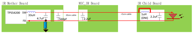
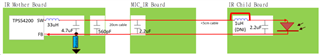
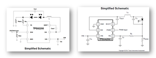
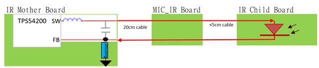
1) How should I connect the high frequency filtering cap or LC filter cap? It should be connect to Rsense as per COUT? Or it should be connect to GND per common filtering concept?

2) Due to the LED+/- will be travel across 3 boards with length >20cm in total, any suggestion for filtering concept needed? For example any suggested filter cap value or formula needed to include in this design for precaution purpose.

Thanks and regards,

ZL Woon

  • Hi ZL,

    1) The filtering capacitor should be connected in parallel with the LED.

    2) I would recommend placing the filtering cap closer to the LED side to reduce the effects of wire inductance on the AC impedance of the capacitor.

    BR,

    Steven

  • Hi Steven,

    Even the high frequency filtering cap like 100pF to 560pF also connected parallel with LED instead of shunt to GND? 

    Any reason this TPS54200 is specially connect in this way? As i found TPS92200 LC filter is connected to GND instead of parallel to LED.

    Please advice for the components added by me as below.

    Thanks and regards,

    ZL Woon

  • Hi ZL,

    • For the smaller capacitor, connect it in parallel with the large capacitor and close to the LED if you would like to filter out some high frequency current ripple / noise on LED.
    • Actually, I think it would also be OK if you connect the capacitor from the anode of LED to GND. I need to check this point with some senior experts from our team. I will keep you updated once I get the feedback.

    BR,

    Steven

  • Hi Steven, 

    Do you get the feedback from your senior expert?

  • Hi ZL,

    For TPS54200 / TPS92200, it would be both ok to connect the capacitor from LED anode to LED cathode or from LED anode to GND. The main difference is shown below:

    • When you connect the capacitor from LED anode to LED cathode, the inductor current is sensed. This may make the feedback loop more sensitive and faster.
    • When you connect the capacitor from LED anode to GND, the LED current is sensed (which may lag behind the inductor current). This may make the feedback loop a bit slower but the LED current is more accurate (because the LED current is sensed and stabilized).

    Best Regards,

    Steven

  • Hi Steven,

    Is that okay if I connect both way at the same time, which is 1x22uF from LED anode to LED cathode, and another 1x22uF from LED anode to GND?

  • Hi Steven,

    I would like to top up and compile the questions as below:

    1) Is that okay if I connect both way at the same time, which is 1x22uF from LED anode to LED cathode, and another 1x22uF from LED anode to GND? Any compromise cause stability issue?

    2) In this case, the best placement will be parallel cap (LED anode to LED cathode) just after inductor, and the shunt cap (LED anode to GND) must be as near to LED as possible?

    3) Is the above capacitors will be impact to the RC filter selection at FB pin?

  • 4) Any formula or capacitance range to select the parallel cap (LED anode to LED cathode)?

  • Hi ZL,

    1) Since you are using TPS92200D2 with analog dimming. So I think capacitors from LED anode to GND is more suitable for you because it can produce more accurate LED current. I do not think you need the capacitors from LED anode to LED cathode unless you do see a need from your test (for example, you see the LED current has a large ripple). Having additional capacitors can make the feedback loop more complex and you need to be more careful.

    2) Placing the cap from LED anode to GND close to the IC is recommended.

    3) Yes. They are both parts of the loop. My advice is that only add the RC filter when you do need it.

    Best Regards,

    Steven

  • Hi Steven,

    2) In case TPS9220 IR signals need to travel across few boards as below, I think I need to add few capacitors to filter any high frequency noise and low frequency ripple at other boards. Thus, capacitors from LED anode to GND or capacitors from LED anode to LED cathode is better solutions? or need implement both?


    3) How to define that only add the RC filter when need it? And do you able to get the RC filter selection guideline since TPS92200 do not have this statement?

  • Hi ZL,

    2) I think you can implement both.

    3) I am currently trying to find some design guidance for TPS92200 RC filter selection.

    BR,

    Steven

  • Hi Steven,

    2) I assume TPS92200 also can implement both, am i right? But how do I define which method is better or higher priority? Based on selected driver?

    Since you can see that the recommendation application circuit is different between TPS92200 and TPS54200. 

    3) Any update for the design guidance?

  • Hi ZL,

    2) Yes. You are right. The connection shown in the datasheet is of higher priority and you should follow that first. Then if needed, you can add extra capacitors / filtering circuits.

    3) You can refer to this application report - www.ti.com/.../slvaei7

    BR,

    Steven

  • Hi Steven,

    3) The document explained about single pole created by LC filter, but there is no FB pin RC filter selection guideline for either analog diming and PWM dimming mode as per stated in YPS54200.

  • Hi ZL,

    Well. Understood your point. I think we still need to check the internal design. I have pushed the progress for you.

    BR,

    Steven

  • Hi Steven,

    Any update for the design guidance of TPS92200 RC filter selection?


  • Hi ZL,

    Let me check with the design team to see if they have some updates.

    BR, Steven

  • Hi ZL,

    The design team has already done some research and they said they will wrap things up and feedback to me before next Tuesday.

    BR, Steven

  • Hi ZL,

    Thanks for your patience. We have analyzed the internal circuitry of TPS54200/1 and TPS92200. Below is our final conclusion for TPS92200 / TPS54200 output capacitor and the FB filter design.

    Regarding the output capacitor location,

    • For TPS92200, the output capacitor should be placed from LED anode to GND.
    • For TPS54200/1, the output capacitor should be placed from LED anode to LED cathode.

    Regarding the FB filter design,

    • For TPS92200, no RC filter is needed for FB pin. You can add a <= 1kohm resistor R_FB, if needed, as shown below to filter out some high-frequency noise from going into the FB pin, but no capacitor should be placed from FB pin to GND.
    • For TPS54200/1, an RC filter is needed for FB pin. Please refer to Section 9.2.1.2.4 FB Pin RC Filter Selection from the datasheet to design the filter.

    Best Regards,

    Steven