This thread has been locked.

If you have a related question, please click the "Ask a related question" button in the top right corner. The newly created question will be automatically linked to this question.

TPS92200: TPS92200 vs TPS54200 assessment study

Part Number: TPS92200
Other Parts Discussed in Thread: TPS54200

Hi TI,

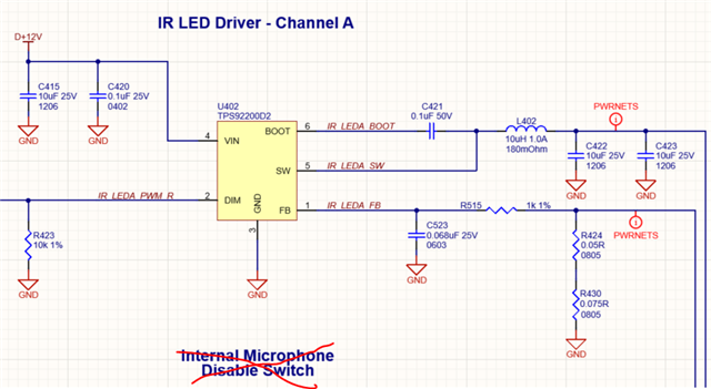
I am currently make assessment to study for part selection between TPS92200 and TPS54200.

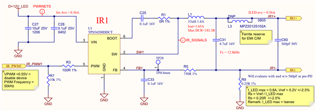
My previous products are using TPS54200 until recently TPS92200 is being introduced as a replacement for TPS54200.

Based on TI, what is improvement has been done on TPS92200 compared to TPS54200 since it is the next generation?

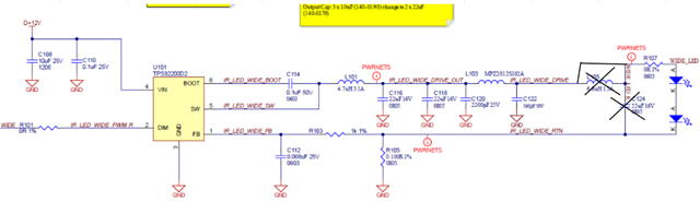
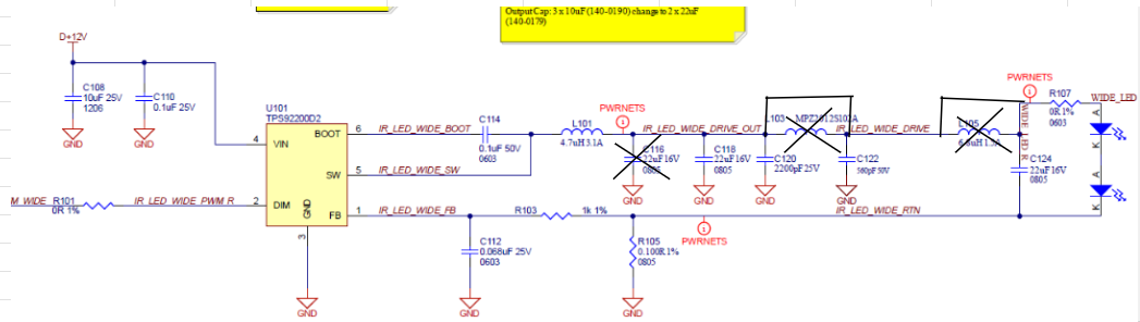
My new product application as below:

Input voltage: 12V +/-5%

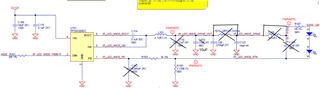
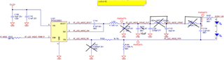
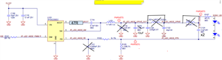
LED used: SFH4715 (same as datasheet typical application circuit)

Qty of LED used: 2

Vo: ~6.2V (included 200mV Vsense if analog dimming in TPS54200)

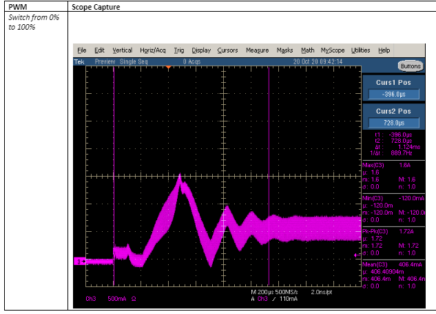
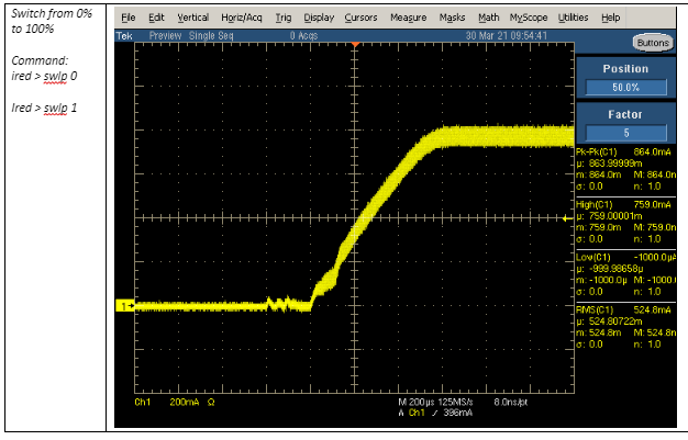
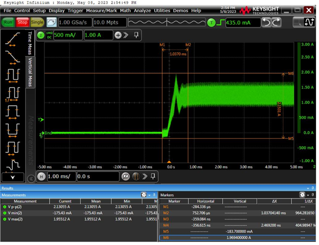
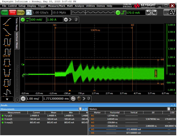
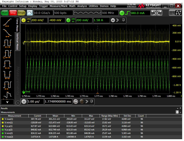
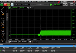
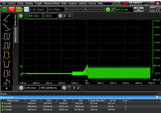
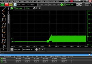
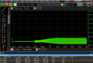
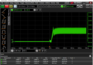
LED current (rms): 200mA to 600mA (to drive LED string)

LED current (max): <1A during 100% duty cycle

Efficiency: >90%

Duty cycle: huge dynamic range which duty cycle input can be changeg from 5% to 95% during operation mode based on environment temperature, but driver still assure loop stability.

Special requirement:

1) Temperature coefficient must be good to reduce fluctuation during operation. 

2) High efficiency due to POE power budget limitation.

3) Small PCB size constraint

Besides, could you please list out the pro and con if I changed to TPS92200? (Ex: price, inventory, thermal performance, noise performance, efficiency performance and etc.)

Thanks and regards,

ZL Woon

  • Hi ZL,

    1. TPS92200 is the next generation of TPS54200. The improvements include:
      1. Wider Vin range
      2. Lower Iq
      3. Higher switching frequency for smaller inductor footprint
      4. More accurate FB pin reference voltage
      5. More options for different dimming requirement (TPS92200D1 and TPS92200D2)
      6. Larger maximum duty cycle
      7. Newer process --> better price and supply
      8. ......
    2. Please double check your Vo for 2 IR-LED.
    3. Ignoring your Vo, the TPS92200 is the best match for your application.

    BR,

    Steven

  • Hi Steven,

    1) Can explain more details on item d.?

    2) Item f. duty cycle = Vo/Vin? (not the PWM duty cycle)

    3) Vo = 6.1V (1 LED Vf = 3V at If = 0.8A, thus 2 LED Vf + Vsense). Any concern?

    4) From the datasheet, it requires >300mA inductor current ripple current become my concern due to higher risk of EMI and also loop stability issue at <10% PWM duty cycle. Why this >300mA is not required for TPS54200?

    5) From my opinion, due to high inductor current ripple of TPS92200, the output cap and filtering cap is critical and must be bigger value (normally bigger size or more per), so it also cause pcb size constraint as well.  

    Thanks and regards,

    ZL Woon

  • Hi ZL,

    1) TPS92200 FB voltage in both analog and PWM dimming: 99 mV ±3 mV

    TPS54200 FB voltage in PWM dimming: 99 mV ±4 mV

    TPS54200 FB voltage in analog dimming: 201mV(MIN) 205mV(TYP) 210mV(MAX)

    Please check Electrical Characteristics from the datasheet for details.

    2) This refers to the buck switching duty cycle, not PWM duty cycle. Sorry for the ambiguity.

    3) I see you mention two IR-LED SFH4715. The forward voltage Vf should not be so high. Please double check.

    4)  As TPS54200 is an old device, I need to check this point with the design team. For the "loop stability issue at <10% PWM duty cycle", is that refer to the oscilloscope capture you posted in this thread? https://e2e.ti.com/support/power-management-group/power-management/f/power-management-forum/1220387/tps92200-inductor-current-ripple-300ma-requirement

    5) I believe the TPS54200 would also have some minimum inductor current ripple requirement as it also uses peak-current-mode. Will check this with design team.

    BR,

    Steven

  • Hi Steven,

    4) Yes. We got product facing loop stability issue when the IL ave is about 80mA with ripple 450mAp-p. 

    5) Please help to get the minimum inductor current ripple for TPS54200 as soon as possible, as we got a few released products are using this TPS54200 designed with 170mAp-p only.

  • Hi ZL,

    4) Please show me the schematic for your TPS54200 circuit facing loop stability issue.

    5) Will do. Please noticed that the inductor current ripple requirement is just a guidance, the final application needs to be tested.

    Best Regards,

    Steven

  • Hi Steven,

    The loop stability issue during load transient test is from TPS92200. You can refer to the below schematic.

    So far, the TPS54200 from previous product tested no load transient issue due to we didnt follow the >300mA inductor, thus the inductor is big enough to meet 30% CR. Below is the TPS54200 schematic.

    In short, previous product result make me uncomfortable to use the next generation, which is TPS92200 although it is cheaper.

  • Hi ZL, 

    Our experts in China are on holiday this week.  Please expect delay in response.

    Best regards,

    Dave

  • Hi Steven and Dave,

    Any update from the experts in China? 

    ZL Woon

  • Hi ZL,

    • For TPS54200, this is an old device. We need some time to access the database and check its internal circuity.
    • Let's focus on TPS92200 first, for the load transient problem, I will try to re-produce it on our EVM tomorrow. What load (how many LEDs) are you using? What's the signal frequency at DIM pin? Please provide more details for me to re-produce the problem.

    Best Regards,

    Steven

  • Hi Steven,

    I am just evaluating a prototype pcb as below.

    DIM frequency = 50kHz

    2 LEDs 

    Green signal: Inductor current (DC)

    Yellow signal: Vout (AC)

    Condition 1:

    Waveform:

    Figure 1: Load transient from 0% to 100% PWM duty cycle

    Figure 2: Load transient from 0% to 2% PWM duty cycle

    Figure 3: Operating with max load 

    Condition 2:

    Waveform:

    Figure 4: Load transient from 0% to 100% PWM duty cycle

    Figure 5: Load transient from 0% to 2% PWM duty cycle

    Figure 6: Operating with max load

    Condition 3:

    Waveform:

    Figure 7: Load transient from 0% to 100% PWM duty cycle

    Figure 8: Load transient from 0% to 2% PWM duty cycle

    Figure 9: Operating with max load

    Condition 4:

    Waveform:

    Figure 10: Load transient from 0% to 100% PWM duty cycle

    Figure 11: Load transient from 0% to 2% PWM duty cycle

    Figure 12: Operating with max load

  • Summary of my observation:

    1) Parallel cap with LED improve the load transient especially for low light condition.

    2) Cout to GND can improve the Vo ripple current, but higher capacitance can cause higher inrush during load transient.

    Please correct me if i am wrong.

    Question:

    1) Is there any equation to calculate the required capacitance to GND and parallel with LED in order to optimize the load transient and ripple voltage? Or tuning on board is necessary?

    2) I am still studying to remove the high frequency noise which occur at every peak of inductor, it is very high especially max load. Do you have any proposal or idea?

  • Hi ZL,

    I test the circuit below. Load: 2 IR-LED. Input: 12V. TP7 input: 50kHz PWM

    The only output filter is a 10uF capacitor. And I do not observe any instability and load transient problems.

    Below is the oscilloscope capture for dimming ratio change from 1%-->99%. Red: SW voltage. Orange: LED current. Light blue: LED anode voltage. Dark blue: inductor current.

    Below is the oscilloscope  capture for start-up at 100% duty cycle. Red: SW voltage. Orange: LED current. Light blue: LED anode voltage. Dark blue: inductor current.

    You can try below steps to see if the load transient problems can be resolved.

    • Do not install the C112 in your circuit above and see if the problem is resolved.
    • Simplify your output filtering circuit, reduce the output capacitor value and see if the problem is resolved. Too much output capacitance may lead to instability.

    Best Regards,

    Steven

  • Hi Steven,

    I able to duplicate the same waveform after removing C112, but do you try your EVK with light load for example 0% to 2% or 0% to 20%?

    My result as below which is still have some inrush current during startup.

    Green signal: Inductor current

    Condition 1: Remain 1x 10uF output capacitance to GND only, remove C112.

    Figure 1: 0% to 20% load transient.

    Figure 2: 0% to 2% load transient

    Condition 2: Add 1x 22uF output capacitor parallel with LED.

    Figure 3: 0% to 20% load transient.

    Figure 4: 0% to 2% load transient.

    Beside, the C112 and R103 are added previously in order to reduce the FB signal spike as below.

    Please advise whether C112 able to remove in order to improve the load transient at heavy load but end up increase FB pin spike.

  • Beside, there is added 47ohm resistor series with boost capacitor in order to reduce the switching noise caused by high current ripple of inductor. While I also added 1 more 22uF capacitor parallel with LED in order to reduce the output ripple. 

    Please advice for any side effect caused by the new added components? Efficiency drop?

    Measurement result:

  • Hi ZL,

    • C112 and R103 can be used to filter out unwanted noise on the FB pin, but their value should be carefully designed. Otherwise, the loop response may be adversely impacted.
    • Could you send me a clearer oscilloscope capture of the noise on FB pin? (The above one is not clear) How did you test those noise? Under what condition?
    • For the 0%-2% and 0%-20% condition, I will do a test next Monday and give you a feedback.

    Best Regards,

    Steven

  • Hi Steven,

    I copied the TPS54200 FB pin RC filter statement as below, but it can't be found in TPS92200. Is that the TPS92200 have to meet the same requirement?

    Before remove the C112, the FB pin measured as below:

    Figure 1: FB pin with 50mV vertical scale

    But when i remove the C112, the FB pin measured as below:

    Figure 2: FB pin with 200mV vertical scale

    Figure 3: FB pin after zoom in

    My questions as below:

    1) In short, the unwanted spike have to be reduced to prevent loop stability issue, am I right? 

    2) Any spec for the overshoot, undershoot and duration to prevent loop stability issue?

    3) In case the RC filter must be placed, then the load transient at light load issue will be resume. So, the only improvement can be done is add a parallel cap with LED? Please advice.

    4) Could you try to add C112 at your side to measure the Inductor current during startup and also VFB pin during max load?

  • Hi Steven,

    I would like to replace the figure 2 and 3 with higher bandwidth and setup as below:

    Figure 2: FB pin with 200mV vertical scale 

    Figure 3: FB pin after zoom in

  • Hi ZL,

    Regarding your questions, please see my comments below:

    (1) The extra 47ohm resistor series with boost capacitor can be used to mitigate EMI. But it will reduce the turn-on speed of the high-side FET and cause more switching loss, and therefore lower efficiency. The selection of its value is a tradeoff.

    (2) I do not think it is necessary to add the 22uF capacitor parallel with LED, unless you observe large LED current ripple.

    (3) TPS92200 should have similar FB pin RC filter selection guidelines, but the numerical values may not be the same. I will have a check.

    (4) You are right. The unwanted spike havs to be reduced to prevent loop stability issue. From your result, basically you need a RC filter to filter out the 666MHz ringing.

    (5) We do not have any specific spec for the overshoot, undershoot and duration to prevent loop stability issue.

    (6) I will try to add C112 at my side to measure the inductor current during startup and also VFB pin during max load.

  • Hi Steven,

    Before you add the C112, you are still need to check the load transient when 0% to 20% and 0% to 2% during startup test. 

    In case the C112 is needed to reduce the unwanted spike, do you still have any other proposal to solve the load transient issue during startup? Since you think parallel cap is unnecessary. 

  • Hi ZL,

    Well noted. Should be able to do a bench test tomorrow and will feedback to you then.

    BR,

    Steven

  • Hi Steven, 

    Any update for the bench test result? 

    Besides, please help to confirm whether TPS92200 has the FB pin RC filter selection guidelines. I think some people might just follow the old version driver for example TPS54200, which I worry it is actually consider as missuse or mistake. 

  • Hi ZL,

    Sorry for the delay. Will update here later today.

    BR,

    Steven

  • Hi ZL,

    Below is the result from below circuit. Load: 2 IR-LED. Input: 12V. TP7 input: 50kHz PWM

    Black curve is measured at TP7 as shown above. Light blue: SW voltage. Orange: inductor current. Dark blue: LED current.

    Figure1: 0% - 20% start-up capture

    Figure 2: 0% - 2% start-up capture

    There are some overshoot in the set-up process of LED current. But I think that is in the acceptable range since the overshoot is not big and not last long. 

    Best Regards,

    Steven

  • Hi Steven, 

    How about the test result after adding the RC filter at FB pin?

  • Supplement:

    This is tested with the same circuit as above, except that C6 = 0.068uF is fitted.

    Black curve is measured at TP7 as shown above. Light blue: SW voltage. Orange: inductor current. Dark blue: LED current.

    Figure 1: 0-20% start-up capture

    Figure 2: 0-2% start-up capture

    Figure 3: 0-99% start-up capture

    Figure 4: 1% - 99% transient response

    Figure 5: 0-100% start-up capture

    The adding of the 0.068uF cap makes the loop a bit unstable. This can be clearly observed from Figure 4. It also makes the transient response poor. So I do not think adding the 0.068uF here is a wise choice.

    The pole added here has the frequency of 1 / (2*pi*R*C) = 2.34kHz. I do not think TPS92200 employs the same criteria for adding the pole with TPS54200 (The appropriate value range may be different.) I will verify this by looking into the design details later.

    BR,

    Steven

  • Hi Steven,

    You can try to add a parallel 10uF or 22uF capacitor to LED, the transient response should be able to improve. Let me know your test result after adding it.

  • Hi ZL,

    Yes, I believe adding a paralleling 10uf or 22uF capacitor to LED can help reduce the transient problem on the LED current. But if the inductor current still show abnormal transient waveform as above (like Figure 2 from my previous reply), the feedback loop is still unstable due to the adding pole and this still needs to be resolved by removing this pole (or moving it to a more appropriate position). 

    Best Regards,

    Steven

  • HI Steven,

    Based on Figure 3 and Figure 4, the transient responses from 0% to 99% and 1% to 99% are different. Any reason?

  • Hi ZL,

    That is a difference between start-up behavior and transient behavior.

    • Figure3: the system is disabled before 99% duty cycle.
    • Figure4: the system has already been enabled (in 1% duty cycle) before 99% duty cycle.

    Best Regards,

    Steven

  • Hi Steven,

    Understand. But why after enabled only step up to 99% duty cycle will have worse transient response?

  • Hi ZL,

    Sorry but please clarify which two conditions you are comparing.

    Best Regards,

    Steven

  • Hi Steven,

    • Figure3: the system is disabled before 99% duty cycle.
    • Figure4: the system has already been enabled (in 1% duty cycle) before 99% duty cycle.

    I would like to know the reason behind that cause the different transient response between start-up behaviour and transient behaviour.

  • Hi ZL,

    That's hard to say as the loop is already unstable (or near-unstable). A possible reason may be that the output capacitor C5 is already charged in Figure4. But the C5 is not charged in Figure3 and can make the system prone to overshoot. 

    Best Regards,

    Steven