This thread has been locked.

If you have a related question, please click the "Ask a related question" button in the top right corner. The newly created question will be automatically linked to this question.

TPS55160-Q1: issues about EMI(CE) Noise & Ripple.

Part Number: TPS55160-Q1

Dear TI Engineers.

I have some issues about EMI(CE) Noise & Ripple.

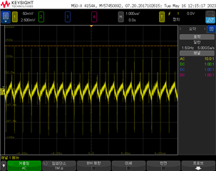
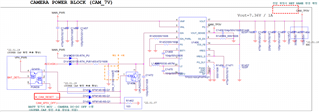
1. Issue: EMC (CE) Fail due to Ripple & Noise in the output of TPS55160QPWPRQ1 being used as CAMERA POWER.

- 100Mhz Band Fail (10db over)

2. Low-frequency noise is reduced by applying a lower inductance component

- Inductor. Spec : 3.3 ~ 6.2uH
- Currently applied value: 4.7uH [EMC Fail]
- Value applied after debugging: 1.5uH [EMC Pass]

3. Additional debugging

- No change in Ripple & Noise even when a 4.7uH inductor with a low DCR value and a large current capacity is applied.

4. Inquiries

- Ask if 1.5uH lower than the Min. value of 3.3uH is available.
- Inquire about additional ways to output clean power.

Thanks.

  • Hi Dongpil,

    Thanks for reaching out.

    What is your application and product type?

    What is the input voltage range, output voltage, max output current? Can you reply with the schematic and layout so we can review the design?

    Do you have any waveforms of ripple noise of iL and Vout at the steady state?

    Regards,

    Bryce

  • Dear, Bryce

    Thank you for your help

    1. Application : Car Built-in Camera (DVRS)

    2. Schematic, Layout, Ripple&Noise AC Freq : Upload

    3. Electrical Spec.
    - Vin : 14V
    - Vout : 7.3V
    - Imax : 550mA

    4. Debugging History
    - Capacitor of Vin_10pF, 100pF, 1nF, 10nF, 100nF, 10uF : No effect
    - Capacitor of Vout_10pF, 100pF, 1nF, 10nF, 100nF, 10uF : No effect
    - Placed 100pF in parellel to R1449(feedback resistor) : No effect
    - L1404(4.7uH --> 1.5uH) : Effect

    Most importantly, is it okay to use a 1.5uH inductor?

    Thanks.

  • Hi Dongpil,

    Thanks for detailed feedback.

    Please see my comments below:

    1. Because this device is internal compensated, so the device selection is more important, it is more recommended to use the TI recommended external components.

    2. About the schematic and layout:

    (1) You can fload SS_EN pin to enable spread spectrum function which is helpful to EMI test;

    (2) You can add RC snubber at LX1 and LX2 to ground to help decrease the driving speed;

    (3) I don't any Cin cap close to Vin and ground pin which will increase the Buck switching leg parasitic inductance and is bad for EMI, recommend to put a 0402 0.1uF cap close to Vin and gnd pins.

    (4) Why the Vout_Sense pin is connected to 6P5V but not 7P3V?

    3. About the test waveform, do you test the ripple voltage using the tip and barrel method like below? 

    https://e2e.ti.com/blogs_/b/powerhouse/posts/how-you-measure-your-ripple-can-make-you-or-break-you

    Regards,

    Bryce

  • Dear, Bryce

    1. Because this device is internal compensated, so the device selection is more important, it is more recommended to use the TI recommended external components.

    --> I understand your feedback. but are there any cases where other customers using TPS55160-Q1 changed the INDUCTOR value?

    2. About the schematic and layout:

    (1) You can fload SS_EN pin to enable spread spectrum function which is helpful to EMI test;

    --> No effect (Already activated). 

    (2) You can add RC snubber at LX1 and LX2 to ground to help decrease the driving speed;

    --> There is a change in the ripple waveform(Reduced overshoot, undershoot in PWM waveform).

    --> But the EMI CE test fails.

    (3) I don't any Cin cap close to Vin and ground pin which will increase the Buck switching leg parasitic inductance and is bad for EMI, recommend to put a 0402 0.1uF cap close to Vin and gnd pins.

    --> No effect.

    (4) Why the Vout_Sense pin is connected to 6P5V but not 7P3V?

    --> I uploaded the old SCH, and  Attached the new SCH.

    3. About the test waveform, do you test the ripple voltage using the tip and barrel method like below?

    e2e.ti.com/.../how-you-measure-your-ripple-can-make-you-or-break-you

    --> Yes. I used the clip on method.

    Thanks.

  • Hi Dongpil,

    Thanks for feedback.

    1. I have not seen other customers use inductors out of TI's recommendation. It is no recommend from TI's aspect.

    2. Have you designed the EMI filter at the input side? What about modify the filter parameters?

    3. Have you tested at the output MLCC cap nearest the Vout-GND pins?

    Regards,

    Bryce

  • Hi Dongpil,

    We have not seen an update from you for four weeks, so I assume the questions are answered.

    I close this thread now. If there is still something open, please reply and the thread will get opened again.

    If you have any other question or of the thread has been locked, please open a new one.

    Best regards,

    Bryce