This thread has been locked.

If you have a related question, please click the "Ask a related question" button in the top right corner. The newly created question will be automatically linked to this question.

LM5023-2NBEVM: Problem with output voltage regulation

Part Number: LM5023-2NBEVM
Other Parts Discussed in Thread: LMV431, LM5023, TL431, TL432

Hello, 

I am working with a design similar to the LM5023 65W Evaluation Board. In this design I had changed the shunt voltage regulator from LMV431 (ref voltage: 1.25V) to TL431 (ref voltage: 2.5V). Keeping other components same as recommended in Evaluation Board. 

For 19V output, I had used the potential divider circuit with resistances of 120kOhm and 18kOhm to provide around 2.5V at reference pin of TL431 as shown in following figure.

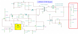
The tina simulation runs fine as expected and 2.49V is obtained at reference voltage pin as shown in following figure.

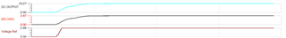
But when this same circuit is applied on PCB, then the output voltage is regulating at 3.8V instead of 19V. Even the voltage at voltage reference pin of TL431 comes around 1.8V instead of 2.5V.    

My plant side is working fine when I checked the converter by providing the fixed duty externally to the gate of mosfet. The problem may be on feedback loop.

Kindly help me with this issue.

Regards, 

Raj

  • Hello Raj, 

    Thank you for your interest in the LM5023 QR flyback controller. 

    I think the main problem is that the pin numbering assignment of the TL431 for REF and cathode are reversed from that of the LMV431.
    You probably need to use the TL432 regulator to drop onto the LMV431 footprint. 
    Prior to obtaining the correct parts, you can test this out by placing the TL431 upside down onto the pads, and using solder blobs to connect the pads to the legs.
    Once correct operation is verified, you can decide what to do next. 

    Aside from that, I recommend to add a 560ohm resistor across the opto-coupler diode to provide a path for the higher bias current needed by the TL43x. 
    Without this resistor, the TL43x will draw some current through the diode which may limit the ability of the converter to deliver full output power.  

    Regards,
    Ulrich

  • Hello Ulrich,

    Thanks for the reply.

    I had noticed that the footprint was the issue. Then placed TL431 through hole with correct configuration, but after that my output voltage settles around 15.6V instead of 19V. (without any parallel resistor across optocoupler diode)

    I had also added one 549Ohm resistor as suggested by you but in this case the output voltage reach 19V then drop down to 0V gradually. I think some protection was triggered in this situation.

    Regards,

    Raj

  • Hello Raj, 

    Without the 549 resistor across the opto-diode, the TL431 must derive its bias current through the opto-diode (rather than around it), and that bias current is then reflected to the primary COMP in by the CTR of the optocoupler.  If the CTR is high, it will pull COMP low which limits the peak current per switching cycle and limits how much energy can be delivered to the secondary.  That explains why you see only ~15.6V without the parallel resistor.   
    Adding the bias resistor shunts the bias current around the diode and allows COMP to stay high during start up and full load operation. 

    I agree that your 19-V start-up probably hit a protection limit.  You describe it as going to 19V and then dropping to zero without repeat.  The LM5023 OVP is a latching fault which requires VDD to fall < 5V to reset.  OVP is detected at the QR pin at a 3-V threshold.  There is no turns-ratio information in your schematic diagram.  I suggest that you examine the OV threshold of your actual circuit based on the resistor values on QR and the Sec-to-Aux turns ratio of your transformer, and make adjustments as needed. 

    Your feedback loop may have some overshoot depending on system conditions, since the compensation values shown above are those of the LM5023 EVM board but may not be appropriate for your actual circuit, having been modified from the EVM.  If you set the OVP fairly high (but still within component ratings), you can check for overshoot in the loop response, revise the compensation to appropriately dampen the response, then reset the OVP to a more protective level. 

    Regards,
    Ulrich

  • Hello Ulrich, 

    Thanks for the detailed explanation. I think first testing with LMV431 is a better option for now, as it will reduce addition of any components.

    Thanks and Regards,

    Raj