We are using fallowing TPS54200DDC IR LED driver ckt in our existing Two Designs.
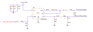
CKT USED is both the design is same.
PWM frequency and Voltage (0-1.8V) is also same.
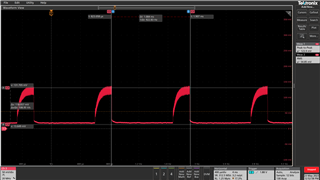
Designs 1:
VIN => 12 V
Observation: here the peak Voltage across is 100 mV which is as per the datasheet 8.4.4 PWM Dimming-Mode Operation.
Waveform: Measurement across RSENSE(R123-100 mE)
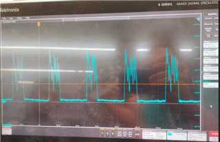
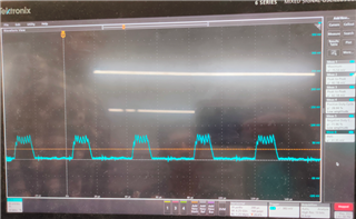
Design 2:
VIN => 5V
Observation: the peak Voltage across RSENSE should be 100 mV as per the datasheet 8.4.4 PWM Dimming-Mode Operation.
Waveform: Measurement across RSENSE(R123-100 mE)
Queries:
- Why TPS54200DDC is behaving differently with different input voltages as the operating voltage is 4.5 to 28V.
- What will be the limitation if its working with 5V.