This thread has been locked.

If you have a related question, please click the "Ask a related question" button in the top right corner. The newly created question will be automatically linked to this question.

TPS54240: Schematic for Synchronizing to system clock

Guru 19565 points
Part Number: TPS54240
Other Parts Discussed in Thread: TPS54340B

Please let me confirm two points below about synchronizing to system clock.

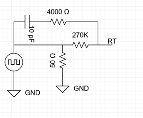
①Is below schematic no problem?

 Clock source is 3.3V CMOS output (Logic IC), it is not Hi-Z.

 Clock source is ON at all the time.

 Logic IC's supply voltage is the same as TPS54240's Vin (5V). 

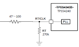
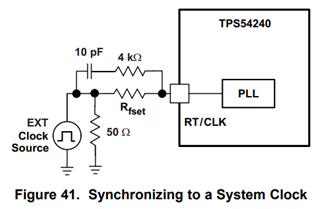
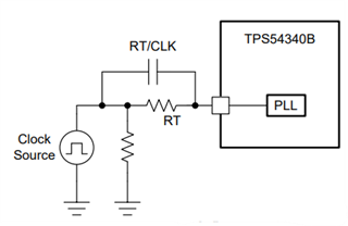
②Datasheet for TPS54240 is described 10pF and 4kΩ, but TPS4340B is deleted 4kΩ.

 What is the background for delete 4kΩ?


Best regards,

Satoshi

  • Hi Satoshi,

    1) It is probably better to do this. The reason this is done was because during testing, the clock had a termination of 50 Ohm. 

    2) TPS54340B can be more immune to jitter which is why 4kOhm resistor is not needed. You may add it just in case. 

    Regards,

    Richard