


HI team,
in researcher i use these two documents.
1: SLVAE09B, Feedback Loop Response Considerations in Peak Current Mode Buck Converter Design,
2: SNVA555, Understanding and Applying Current-Mode Control Theory.
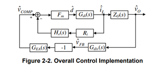
to realize a Current Mode Controle CMC, for SEPIC topology all the explications and notes are clear, except the Sampling Gain,
1) why is it modeled in series with the closed-current feedback loop with Rsns or Ri (the current sensing resistor)?
2) what is the object to add it in the schematic block?
thank you,
