This thread has been locked.

If you have a related question, please click the "Ask a related question" button in the top right corner. The newly created question will be automatically linked to this question.

UCC29002: Stability problem

Part Number: UCC29002
Other Parts Discussed in Thread: UCC28950,

Hello,

My system consists of 3 modules paralleled at 24V and each doing 1100W, for a total load of 3300W. Each module has a UCC28950 and a load share UCC29002D. 

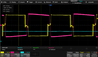
When I run each module independently at full load, I get pretty stable waveforms as seen below in Figure 1.

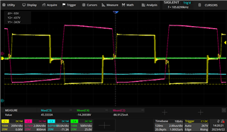
Figure 1: Pink Shim inductor current and Yellow H-bridge on Module 1 (running by itself).

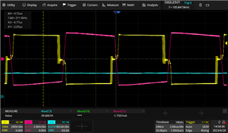
When I run two modules together at full load, my H-bridge and Shim inductor current appear to be pretty unstable like shown below in Figure 2 on both converters. The same occurs when I run 3 modules together.

It is worth noting that each module IS successfully current sharing, it is just the instability that is causing on my system that needs to be solved.

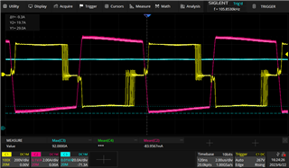
Figure 2: Pink Shim inductor current and Yellow H-bridge on Module 1 (when 2 modules running together).

This is the circuitry regarding the UCC29002D that I have on each module:

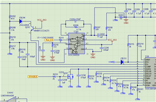
Please let me know if the Load Share has been setup correctly or if there is anything that I can do to solve this problem.

Thank you,

Alberto Miguez

  • Hello Alberto, 

    Thank you for your consideration of the UCC29002 load-share controller. 

    I can't fully review the values of your components, but I do see right off that you are missing 2 parts. 
    The Current Sense amplifier should be configured as a differential amp and you need to add another 4.75K +10nF from CS+ (pin 2) to GND (pin 4).  On each module. 

    Relatively speaking, your CS amp roll-off pole (at ~3.3kHz) is rather close to your EAO zero (~1kHz).  And the EAO zero, which is usually placed at the sharing-loop cross-over, suggests that the sharing cross-over frequency is unusually high.   
    For main PSU switching frequency of ~100kHz, the CS amp can have a noise pole at 1/10th fSW or ~10kHz.  3.3kHz is about 1/30th which isn't excessively low.

    But the share-loop cross-over should be <1/10th of the V-loop cross-over and I wonder if your V-loop crosses at 10kHz? 
    You want your share loop to be very slow compared to the V-loop.   Please double check your PSU cross-over freq and V-loop gain at the targeted share-loop cross-over.  
    A lot of EAO caps I've seen are usually in the 10's of uF range, not down at 470nF.

    Finally, 1100W/24V = 46A through 1mR = 46mV max signal.  CSO gain is 47.5, so max Vcso = 2.1V.  This is leaving a lot of gain capacity on the table.  
    With only 2V of max signal for LS, light-load sharing will degrade faster due to various internal and external offsets affecting the signal when Vcso is small.  
    Assuming VCC_ISO is > 6V, you can easily double the gain and improve sharing.  
    I suggest to increase the gain to as high as possible as long as you keep max Vcso < minimum VCC_ISO.
    Don't forget to reduce the roll-off cap (C220 & Cnew) to maintain the same (or higher) pole.  

    Regards,
    Ulrich

  • Good morning Ulrich. 

    I wanted to start by thanking you for your detailed answer. I really appreciate you helping me with this.

    The C228 from the schematic I shared earlier is currently not populated. 

    So far, I have added a 4.75K+10nF from CS+ to GND as you suggested earlier, as well as increasing the EAO cap from 470nF (C229) to 10uF. Neither change has impacted my waveforms so far. 

    I went through the Excel sheet provided by UCC28950 and came up with this Bode plot based on the parameters in my system: 

    I believe the cross over frequency to be around 5kHz for the UCC28950 in my system.

    I also went to the Excel sheet for the UCC29002 and it recommended I change the C_csa capacitor (C220 &Cnew, which is currently 10nF) to 447 pF by picking a high frequency pole at 75kHz. Is it wise to choose a high frequency pole at 75kHz based on the bode plot from my UCC28950? I would appreciate it if you could advise me on this. 

    The VCC_ISO is 12V, so yes, based on your recommendation I will be increasing the gain to get better accuracy once I have a more stable system.

    Please let me know your thoughts.

    Thank you,

    Alberto

  • Hello Alberto, 

    Thanks for the latest information.  I understand that obtaining the Bode plot for your UCC28950 system is a tedious process, but I think it is important to measure the true frequency response of your power module because it may differ, possibly significantly, from what the Excel tool predicts. 
    The reality may shift your EAO component selections to a possibly lower zero frequency.     
    That said, having the prediction at this point is better than nothing.  

    First, with a switching frequency of ~106kHz (from 'scope shot), I recommend a CSO pole at ~10kHz.  Above, I mentioned that your existing values result in ~3.3kHz pole which is probably okay, but maybe I suggest to raise it up to ~10kHz, using 3.3nF at C220 and Cnew.   75kHz is too close to fSW to be effective, and I think you mistake the default value of 75kHz at cell C44 in the UCC29002 Excel tool as a recommended value.  It is merely a number used by the tool author for an example design from years past.  All yellow-shaded cells should be changed to match your own design parameters and your choice for targets.  I guess the tool is not very clear on this point.  If you put in 10kHz at C44, then C45 should result in a recommendation value close to 3.3nF.

    The load share should only regulate the current (with respect to other modules) but it does so by adjusting Vout slightly. It should do this at a response rate much slower than the loop response of the power module.  From your Excel's Bode plot, I see the module's cross-over = ~3.3kHz.  This means that the load-share loop should cross over at or below 330Hz.  But the V-loop gain is difficult to determine there. 
    I suggest to select load-share cross over at 220Hz, because the gain is obvious at 40dB.  

    However, if you can get a true Bode plot of your module you can design to the actual numbers, rather than hoping the Excel matches reality. 
    I wonder if your module has the same low phase shift (~30 degrees) at 100Hz as seen in your Excel plot.  Maybe that low phase margin combined with another -90 degrees from the load-share pole at DC result in some jitter between the two loops.  (I'm just guessing here; sorry I can't be more definitive.) 

    Recreating your UCC29002 Excel tool, I plug in 2.2 kHz cross-over at C14 to force 220Hz result at C15.
    I put in 0.2W at C31 to get close to your 1mR shunt resistance. 
    I put in 80.6R at C21, but 5% adjustment at C22 results in -130R at C51.  That means that 80R doesn't give enough adjustment voltage for a 5% range. 
    2% at C22 gives a value for Radj > 9717R at C51.  Essentially Radj is open circuit and Rsense of 80.6R will give you only ~0.5V of load-sharing adjustment range.  
    Is it possible to increase R202 to 200R or higher (220, 240, etc.; not too much higher) for better adjustment range of the 6mA available?  

    Putting 1Meg into C52, C56 results in 15uF for EAO cap.  The user selection input at C57 is broken (it should accept your input, but instead it is fixed at 10uF). 
    Reao at C58 is recommended at 515R.  For a zero at 220Hz with Ceao = 15uF, Reao =  48.2R, so I suggest using 47R for Reao.
    Once the loop are stabel and you increase the gain, these EAO values will change. 

    Regards,
    Ulrich

  • Hello again Ulrich,

    I followed your recommendations and placed the 3.3nF in C220 and Cnew, as well as keeping the 10uF in AOE. Neither of them changed my waveforms.

    I then connected a network analyzer to my controller's feedback with the load sharing disconnected. This is the result:

    Figure 1: Bode Plot from Network Analyzer

    Your recommendation should be appropriate since the real bode plot is similar to the estimated one from the Excel sheet.

    I then ran two modules together with the load share disconnected. Module 1 was doing 18A, and Module 3 was doing 10A (as expected since load share is disconnected). I did notice that my waveform did not change either, so the load share was not my problem. I tried connecting them to independent loads, and nothing changed either. 

    For all my testing, I have been using one power supply for the 400V bus voltage that goes into each module. I tried using one power supply for Module 1 and a different power supply for Module 3, instead of running Modules 1 and 3 from the same one. This made a difference:

    Figure 2: 2 Modules running independent from the same power supply

    Figure 3: 2 Modules running independent from independent power supplies

    The current jitter looks a lot better, and the H-bridge also improved a little. Figure 3 looks very similar to the waveform I get when running one module independently (when things are stable). Figure 4's duty cycle looks different because I was running at 24V instead of 28V for this test, but looking at the jitter on the current and voltage, it looks pretty close to Figure 3.

    Figure 4: 1 Module running by itself at 24V 40A

    At this point, I believe my problem is fixed since I will be running each module from isolated power sources from a different board. I will make sure to include your recommendations for the next revision and make sure that things continue to work once I reconnect the load share bus.

    Thank you so much for your support and help.

    -Alberto