This thread has been locked.

If you have a related question, please click the "Ask a related question" button in the top right corner. The newly created question will be automatically linked to this question.

TPS56C215: Question about the Valley current limit in TPS56C215

Part Number: TPS56C215

Hello Tier,

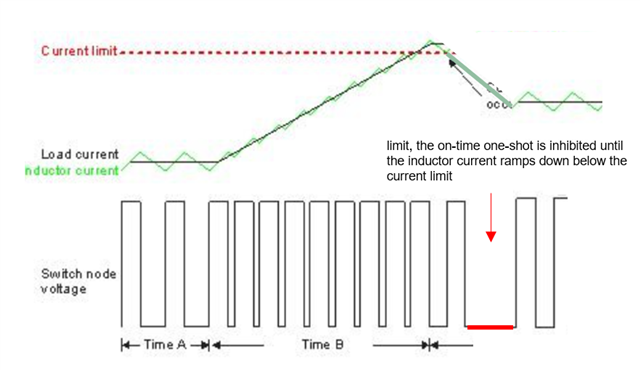
I have a question about the Valley current limit in TPS56C215. I'm afraid of misunderstanding, so I edited a figure in the E2E post for your reference. Can you tell me if the waveform below explains the Valley current limit during Overcurrent?Understanding valley current limit - Power management - Technical articles - TI E2E support forums

Also, can you tell me what is the Current Limit (Low side negative)? Is the current defined as the direction from the source to the Drain of the low side rectifier FET?

  • Hello,

    The bottom figure is correct. negative current limit is set to typical 4A value as per datasheet. This will only occur when you set the device to operate in FCCM using the MODE resistor combinations. If set in eco-mode, the current will not go below zero. If you have set the device to operate in FCCM, during on-time, the current will flow through the HSFET from Vout to VIN. During off-time, the LSFET current that is monitored for 4A valley limit will flow from Vout through inductor to drain to source of the LSFET and back again. During dead-time, HSFET body diode will allow for inductor current to pass through to input supply and caps. Hope this helps.

    Thanks,

    Amod

  • Dear Amod,

    Thank you very much! 

    Could you help us commend the valley current limit question?  

    and further question is do you have Intel test plan experience for DVID down? I found my VR also frequently trigger the LSFET OC negative limit when DVID down.

    kind regards,

    Kuo

  • Hi Kuo,

    Yes the negative current will flow from drain to source of the LSFET. The negative value will be limited to a typical of 4A. I fixed a typo and gave more explanation on the prior reply.

    No, I am not familiar with DVID down causing negative current limit to be hit. As a starting point, please share your schematic that you are using for this experiment along with details of the connections on the load side. Also, please share SW, VOUT and the IOUT or load waveforms when operating correctly and when negative current limit is being triggered.

    Thanks,

    Amod